Pneumatic bridge overweight prevention alarm mechanism
An anti-overweight, pneumatic technology, applied in the direction of alarms, signal devices, instruments, etc., can solve the problems of bridge collapse, casualties, economic losses, etc., and achieve the effect of protecting bridge structure, low maintenance cost and energy saving.
- Summary
- Abstract
- Description
- Claims
- Application Information
AI Technical Summary
Problems solved by technology
Method used
Image
Examples
Embodiment 1
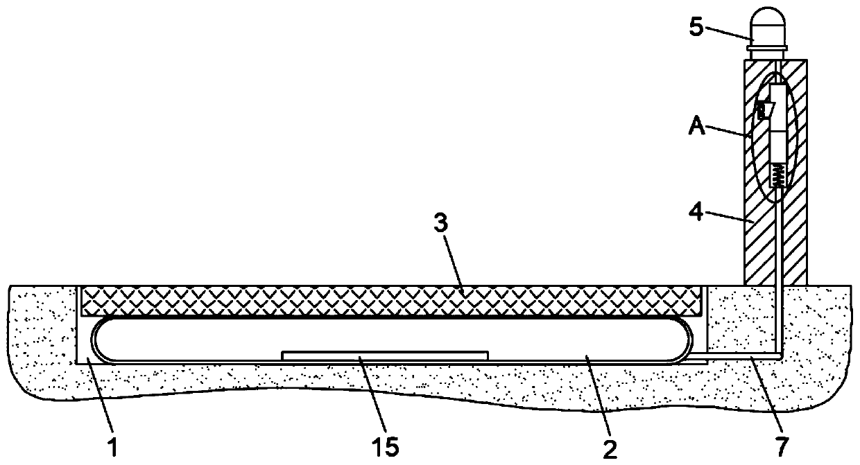
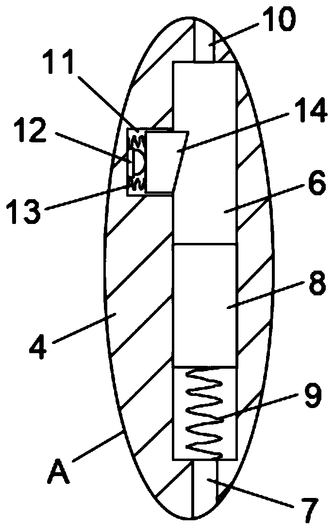
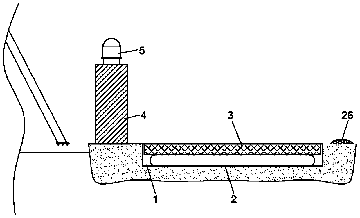
[0022] refer to Figure 1-3 , a pneumatic bridge anti-overweight alarm mechanism, including an installation groove 1 dug on the ground, a buffer airbag 2 is installed in the installation groove 1, and a load-bearing plate 3 adapted to the installation groove 1 is fixed on the upper surface of the buffer airbag 2, A warning platform 4 is fixedly connected to the ground side at the front end of the installation groove 1, and a warning light 5 is fixedly installed on the upper end of the warning platform 4, and the warning light 5 is connected with a self-power supply mechanism, which includes piezoelectric ceramics provided inside the buffer airbag 2 15. The piezoelectric ceramic 15 is electrically connected to the warning light 5 and the key switch 12 in series;
[0023] There is a cavity 6 vertically inside the warning platform 4, a vent pipe 7 is connected between the bottom of the cavity 6 and the buffer air bag 2, and a piston top block 8 is sealed and slidably connected to...
Embodiment 2
[0026] refer to Figure 4-5 , while retaining the other structures of Embodiment 1, the self-power supply mechanism can also adopt a transmission rod 16 vertically welded on the bottom of the front and rear ends of the load-bearing plate 3, and the front and rear side walls of the installation groove 1 are all rotated A group of first gears 17 and second gears 18 meshed with each other are connected, wherein the number of teeth of the first gears 17 is greater than that of the second gears 18, and the side walls of each transmission rod 16 are fixedly connected with the first gears 17 The first gear rack 19 engaged, the bottom of the installation groove 1, the front and rear ends are correspondingly provided with a deep groove 20, and the notches of each of the deep grooves 20 are fixed horizontally with a mounting plate 21, each of which The center of the mounting plate 21 is slidingly connected with a movable rod 22, and the upper side wall of each movable rod 22 is also fix...
PUM
 Abstract
Description
Claims
Application Information
 - R&D
- Intellectual Property
- Life Sciences
- Materials
- Tech Scout
- Unparalleled Data Quality
- Higher Quality Content
- 60% Fewer Hallucinations
Browse by: Latest US Patents, China's latest patents, Technical Efficacy Thesaurus, Application Domain, Technology Topic, Popular Technical Reports.
© 2025 PatSnap. All rights reserved.Legal|Privacy policy|Modern Slavery Act Transparency Statement|Sitemap|About US| Contact US: help@patsnap.com


