Grooving device for camber surface of inner side of shaft sleeve workpiece

A technology for grooving and workpiece, which is applied to the field of camber grooving device on the inner side of the shaft sleeve workpiece, can solve the problems of cumbersome processing process, difficult processing head, long processing cycle, etc., and achieves a high degree of processing automation, reasonable and accurate structural design. The effect of efficient reciprocating translation motion

Active Publication Date: 2019-12-13
常熟市万顺轴承有限公司
View PDF5 Cites 8 Cited by
  • Summary
  • Abstract
  • Description
  • Claims
  • Application Information

AI Technical Summary

Problems solved by technology

The shaft sleeve workpiece is the main type of shaft-type workpiece. The shaft sleeve is a cylindrical mechanical part that is sleeved on the rotating shaft. It is an integral part of the sliding bearing. During the production and processing of the shaft sleeve mechanical workpiece, the shaft sleeve workpiece It needs to go through the processing steps of die-casting, grinding and drilling in sequence. The shaft sleeve workpiece has various types of sizes, specifications and appearance shapes, especially when grooving the inner arc surface of the shaft sleeve with a hemispherical structure. Some processing equipment is difficult to meet the needs of shaft sleeve processing. Because the end of the shaft sleeve is a circular structure, the existing clamping mechanism is difficult to fasten and fix the shaft sleeve conveniently and efficiently. The clamping and fixing of the shaft sleeve causes the shaft sleeve to fall off, and the existing clamping mechanism is difficult to apply to the clamping and fixing of shaft sleeve workpieces of various sizes and specifications, and the scope of application is narrow. Among them, the shaft sleeve is clamped and fixed, and the processing head is adjusted according to the needs, so as to realize the processing of the shaft sleeve. However, due to the complex structure of the processing head and many driving mechanisms, it is difficult for the processing head to The shaft sleeve processing requires convenient and smooth operations such as rotation and translation. It is difficult for the existing shaft sleeve processing mechanism to achieve a stable and accurate rotation and adjustment position after the shaft sleeve is clamped and fixed. Therefore, in the processing process of the existing shaft sleeve workpiece Among them, the processing process is extremely cumbersome, and the processing cycle is also long, which cannot meet the large-scale production and processing of shaft sleeve workpieces. The existing grooving processing mechanism has complex structure and troublesome operation, and it is difficult to perform grooving processing on the arc surface smoothly. The adjustment of the processing cutter head is troublesome. It is difficult to quickly and conveniently adjust the processing cutter head along the inner arc surface of the shaft sleeve, and the adjustment accuracy is poor. Groove processing cannot meet the needs of workpiece processing

Method used


Image

  • Grooving device for camber surface of inner side of shaft sleeve workpiece
  • Grooving device for camber surface of inner side of shaft sleeve workpiece
  • Grooving device for camber surface of inner side of shaft sleeve workpiece

Examples


Embodiment Construction

[0022] In order to further describe the present invention, the specific implementation of a cambered grooving device on the inside of a shaft sleeve workpiece will be further described below in conjunction with the accompanying drawings. The following examples are explanations of the present invention and the present invention is not limited to the following examples.

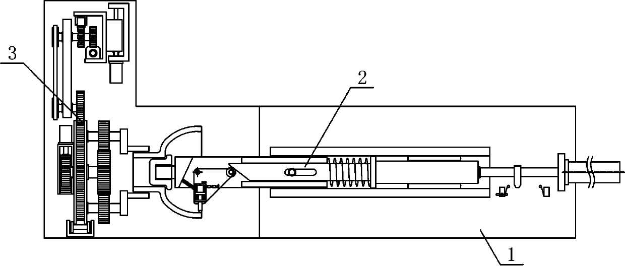
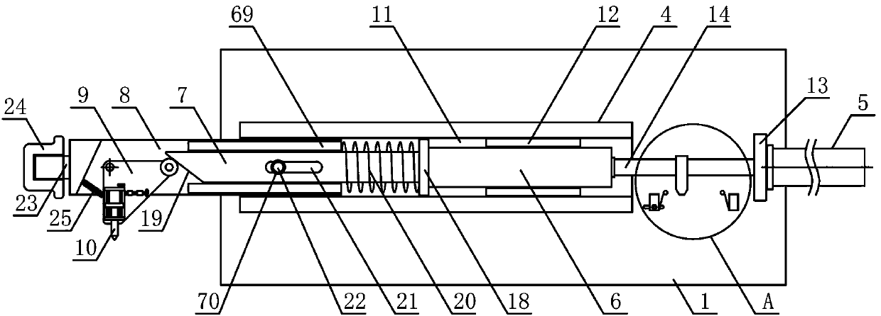
[0023] Such as figure 1 As shown, a device for grooving the inner arc surface of a shaft sleeve workpiece according to the present invention includes a processing bracket 1, a translational grooving mechanism 2 and a workpiece clamping mechanism 3. The translational grooving mechanism 2 is horizontally arranged on the processing bracket 1, and the workpiece clamping mechanism 3 The processing support 1 vertically adjacent to one side of the translation grooving mechanism 2, such as figure 2As shown, the translation grooving mechanism 2 of the present invention includes a translation support 4, a reciprocating ...


PUM


Abstract

The invention discloses a grooving device for a camber surface of the inner side of a shaft sleeve workpiece and belongs to the field of machinery equipment for machining the workpiece. According to the grooving device, a workpiece clamping mechanism is arranged at a machining bracket positioned at one side of a translational grooving mechanism; a translational guide plate is horizontally and slidably arranged on a guide support; a push plate bevel is arranged at the lower side of the end part of a translational pressing plate; the translational pressing plate is slidably arranged at a tool bit bracket; a grooving rotary plate is arranged at the tool bit bracket, positioned along the underside of the end of the push plate bevel, of the translational pressing plate; a machining rotary platerotates along bearing plate rotating wheels; the machining rotary plate positioned at the outer side of a clamping main gear is provided with a plurality of clamping auxiliary gears; a rotary gear ofa driving bracket is engaged with a rotary rack of the machining rotary plate; and a converting bracket is horizontally arranged at one side of a lifting bracket. The grooving device is reasonable instructural design, can be used for efficiently and conveniently clamping and fixing the shaft sleeve workpiece and realizing stable and accurate rotation, thereby realizing automatic grooving machining of the camber surface of the inner side of the shaft sleeve workpiece, achieving a high machining automation degree and meeting the use demands of machining of the workpiece.

Description

technical field [0001] The invention belongs to the field of workpiece processing machinery and equipment, and in particular relates to a device for cutting grooves on the inner arc surface of a shaft sleeve workpiece, which is mainly used in the field of production and processing of shaft sleeve workpieces. Background technique [0002] Mechanical workpieces are single parts that make up machinery and machines that cannot be separated. It plays an important role in the automation industry. Mechanical workpieces include the connection of parts, supporting parts, lubricating lubrication systems and sealing parts. Components, parts of transmission systems that transmit motion and energy, shaft-type workpieces are the main type of workpieces, shaft-type workpieces are suitable for one or more CNC machine tools, shaft-type workpieces are one of the typical workpieces often encountered in hardware accessories 1. It is mainly used to support transmission parts, transmit torque and...

Claims


Application Information

Patent Timeline
Patent Type & Authority Applications(China)
IPC IPC(8): B23B5/40
CPCB23D79/00B23Q3/00B23Q5/10B23Q5/48B23Q15/14
Inventor 黄明珠
Owner 常熟市万顺轴承有限公司
Why Eureka
Try Eureka