
Auxiliary tool for screwing circular die

A technology for auxiliary tooling and circular die, which can be used in tangent devices, manufacturing tools, metal processing equipment, etc., and can solve the problems of long tire assembly time and complicated procedures

Pending Publication Date: 2019-12-13
HANGCHA GRP
View PDF0 Cites 0 Cited by
  • Summary
  • Abstract
  • Description
  • Claims
  • Application Information

AI Technical Summary

Problems solved by technology

[0005] The object of the present invention is to provide an auxiliary tool for screwing the circular die. The auxiliary tool has a simple structure and can twist the circular die without the space limitation in the side circumferential direction of the circular die. complicated question

Method used


Image

  • Auxiliary tool for screwing circular die

Examples


Embodiment Construction

[0021] The following will clearly and completely describe the technical solutions in the embodiments of the present invention with reference to the accompanying drawings in the embodiments of the present invention. Obviously, the described embodiments are only some, not all, embodiments of the present invention. Based on the embodiments of the present invention, all other embodiments obtained by persons of ordinary skill in the art without making creative efforts belong to the protection scope of the present invention.

[0022] In order to enable those skilled in the art to better understand the solution of the present invention, the present invention will be further described in detail below in conjunction with the accompanying drawings and specific embodiments.

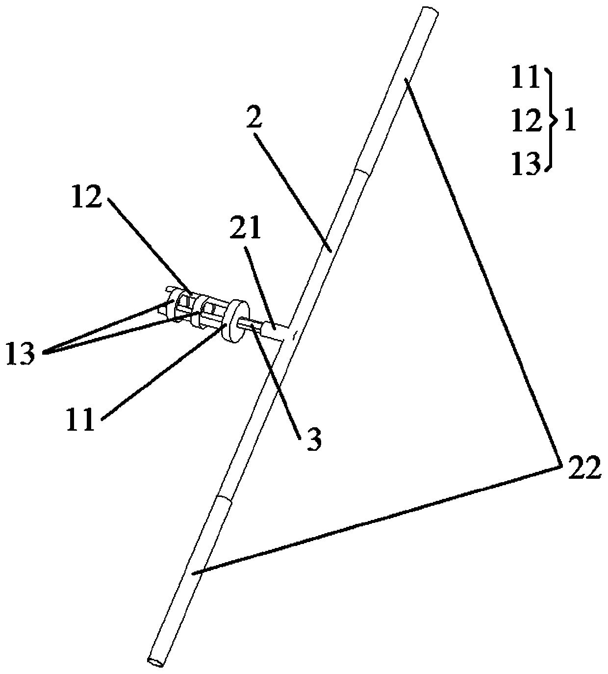
[0023] Please refer to figure 1 , figure 1 It is a structural schematic diagram of an auxiliary tool for screwing a circular die provided by the present invention.

[0024] An auxiliary tool for screwing a circula...


PUM


Abstract

The invention discloses an auxiliary tool for screwing a circular die. The auxiliary tool comprises a clamping portion clamped in a chip hole of the circular die and a driving portion connected to theclamping portion and used for transmitting torque to the clamping portion and achieving rotation of the circular die, wherein the clamping portion comprises a supporting base and a clamping shaft; afirst end of the supporting base is connected to the driving portion; the clamping shaft is arranged at a second end of the supporting base and is clamped in the chip hole of the circular die. The auxiliary tool has a simple structure, can screw the circular die without being limited by the space in the circumferential direction of the circular die, and solves problems of long assembly time and complicated assembly process of tires.

Description

technical field [0001] The invention relates to the technical field of tire assembly, in particular to an auxiliary tool for screwing a circular die. Background technique [0002] In the process of assembling the tires of driving tools, taking forklifts as an example, nuts and bolts are usually used to fix the tires and the frame, but sometimes there may be cases where the bolts and nuts do not cooperate well. The external thread is corrected. [0003] At present, in the process of using circular dies to return wires, because the bolts are located on the concave surface of the tire rim and close to the tire rim, the space between the circular dies and the steel ring is too small, which makes it difficult for common tools such as wrenches to be used with The outer ring of the circular die is connected and drives the circular die to rotate, so the tire has to be removed, and the tire must be reinstalled after the process of returning the wire is completed. [0004] Therefore...

Claims


Application Information

Patent Timeline
Patent Type & Authority Applications(China)
IPC IPC(8): B23G1/44B23G1/02
CPCB23G1/44B23G1/02
Inventor 姜小冬陈瑜何群星洪乐罗德贵
Owner HANGCHA GRP
Learn More