Milling machine fixture

A milling machine fixture, left clamping technology, applied in the direction of clamping, manufacturing tools, supports, etc., can solve the problems of reduced machining accuracy, errors, difficult clamping, etc., achieve the effect of wide application range and avoid machining errors

Pending Publication Date: 2019-12-13
UNIV OF JINAN
View PDF0 Cites 0 Cited by
  • Summary
  • Abstract
  • Description
  • Claims
  • Application Information

AI Technical Summary

Problems solved by technology

[0002] With the development of the manufacturing industry, there are higher requirements for the processing efficiency and precision of parts. Among the fixtures of milling machines currently used, it is difficult to clamp for

Method used


Image

  • Milling machine fixture
  • Milling machine fixture
  • Milling machine fixture

Examples


Example Embodiment

[0014] specific implementation plan

[0015] The technical solutions in the embodiments of the present invention will be clearly and completely described and discussed below in conjunction with the accompanying drawings in the present invention. Obviously, what is described here is only a part of the examples of the present invention, not all examples. Based on the present invention All other embodiments obtained by persons of ordinary skill in the art without creative efforts belong to the protection scope of the present invention.

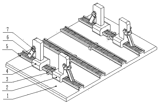
[0016] refer to figure 1 , a milling machine fixture, including a base plate 1, a right clamping part 2, a stopper 3, a left clamping part 4, a guide rail 5, an ejector rod 6, and a bolt 7.

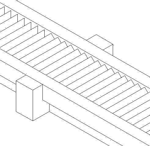
[0017] refer to figure 2 , figure 2 Yes figure 1 Schematic diagram of middle block 3.

[0018] The stopper 3 is welded in the middle of the side of the guide rail 5, the main purpose is to allow the left clamping part 4 to only move on the left side o...


PUM


Abstract

The invention relates to a milling machine fixture. The fixture is arranged in bilateral symmetry, and can be flexibly adjusted according to the shape and size of a processed part. The fixture is provided with a bottom plate which is provided with four guide rails, and a row of regularly arranged protrusions is arranged in the middle of each guide rail. Each guide rail is provided with a right clamping member and a left clamping member, a stopper is arranged at the middle position of the side of each guide rail, and an ejector rod is respectively arranged on the right side of the right clamping member and the left side of the left clamping member. The rear parts of the right and left clamping members and the heads of the ejector rods are provided with through holes of the same size, and the right clamping members and the ejector rods on the right side are connected by bolts. The milling machine fixture has a wide range of applications, and by selecting different guide rails and adjusting the positions of the right and left clamping members, parts of different shapes and sizes can be clamped. Compared with the currently used milling machine fixtures, the error of secondary clampingis avoided and the processing accuracy is ensured when the entire upper surface of the part is milled.

Description

technical field [0001] The invention relates to a fixture, in particular to a milling machine fixture. Background technique [0002] With the development of the manufacturing industry, there are higher requirements for the processing efficiency and precision of parts. Among the fixtures of milling machines currently used, it is difficult to clamp for shaft parts. For other parts, milling the entire upper When surface, it is often necessary to carry out two clamping, which is likely to produce a large error, resulting in a significant decrease in machining accuracy. Contents of the invention [0003] In order to solve the above technical problems, the present invention provides a milling machine fixture. [0004] In order to achieve the above object, the technical solution of the present invention is as follows, a milling machine fixture is characterized in that the left and right sides are symmetrically arranged, including a bottom plate, a right clamping piece, a stopper...

Claims


Application Information

Patent Timeline
IPC IPC(8): B23Q3/06
CPCB23Q3/06
Inventor 刘国栋乔阳段鹏飞
Owner UNIV OF JINAN
Why Eureka
Try Eureka