
Pull rod device with central pipeline and cutter loosening and clamping method

A tie rod device and center tube technology, which is applied in positioning devices, clamping, manufacturing tools, etc., can solve the problems of inability to blow out airflow, affecting the machining accuracy of the spindle, and difficulty in meeting machining requirements.

Pending Publication Date: 2019-12-13
深圳市爱贝科精密工业股份有限公司
View PDF0 Cites 0 Cited by
  • Summary
  • Abstract
  • Description
  • Claims
  • Application Information

AI Technical Summary

Problems solved by technology

[0002] The electric spindle is a mechanical device used on machine tools to achieve precision machining. The existing electric spindle involves the steps of loosening and clamping the tool during the tool change process. When releasing the tool, the tool handle needs to be moved by the airflow of the central air circuit. Clean, but after the knife is clamped, the air flow cannot be blown out due to the closure of the air passage. It can be seen that the center air path inside the pull rod device in the prior art only has the function of cleaning the handle of the knife, and after the knife is clamped, because of The gas path is closed and the air flow in the central air path fails to play any role, so the utilization rate of the air flow is low
In addition, the tool holder and tool will generate a lot of heat during the machining process. If the tool holder and tool cannot be cooled effectively, it will seriously affect the machining accuracy of the spindle, making it difficult to meet the processing requirements.

Method used


Image

  • Pull rod device with central pipeline and cutter loosening and clamping method

Examples


Embodiment Construction

[0017] 下面结合附图和实施例对本发明作更加详细的描述。

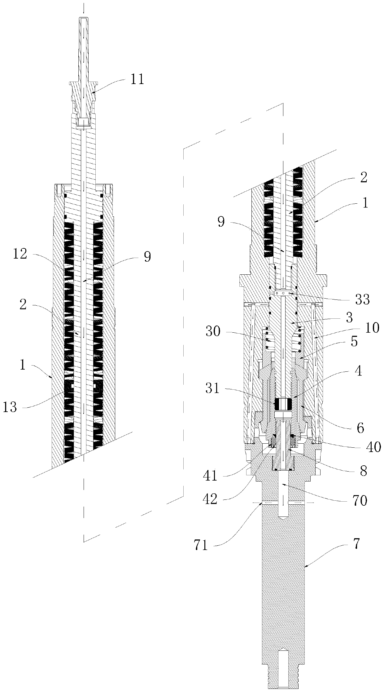
[0018] 本发明公开了一种具有中心管路的拉杆装置,请参见 figure 1 ,其包括有转子1,所述转子1内设有拉杆2、前连接杆3、撑杆4和拉爪座5,所述前连接杆3固定于所述拉杆2的前端,所述撑杆 4固定于所述前连接杆3的前端,所述拉爪座5套设于所述前连接杆3的外侧且二者活动连接,所述拉爪座5的前端设有拉爪6,所 Related claw 6 surrounds the support rod 4. The front end of the rotor 1 has a knife handle 7. 卡设于所述拉爪6与所述转子1之间;

[0019] 所述拉杆2、前连接杆3和撑杆4均呈中空状,所述刀柄7后端的中心处固定有内冷管8,所述内冷管8插设于所述撑杆4的前端,所述刀柄7内开设有刀柄气道70,所述拉杆2、前连接杆3、撑杆4、内冷管8和刀柄气道70依次连通而形成中心管路9,所述刀柄7的侧部开设有与所述刀柄气道70相互连通的刀柄气孔71。

[0020] 上述装置中,所述刀柄7上设置了刀柄气道70和刀柄气孔71,所以在松刀时,利用所述拉杆2带动所述前连接杆3和撑杆4向前滑动,使得 所述撑杆4与所述拉爪6分离,所述拉爪6弹性复位,所述刀柄7被松开,利用所述撑杆4将所述刀柄7顶出,同时,由所述 The back end of the trolley 2 is injected into the airflow within the center pipeline 9, and the knife handle 7 is cleaned by the airflow; when the main axis executes the knife movement, the tie rod 2 drives the front connector 3 and the supporting support. 杆4向后滑动,利用所述撑杆4将所述拉爪6撑开,将所述刀柄7的后端夹紧于所述拉爪6与所述转子1之间,同时,由所 述拉杆2的后端向所述中心管路9内注入气流或者水流,该气流或者水流经由刀柄气道70和刀柄气孔71向外喷出,进而对所述刀柄7以及安装于所 述刀柄7上的刀具进行降温。 In the...


PUM


Abstract

The invention discloses a pull rod device with a central pipeline. The pull rod device with the central pipeline comprises a rotor, wherein a pull rod, a front connecting rod, a support rod and a pullclaw seat are arranged in the rotor; the front connecting rod is fixed at the front end of the pull rod; the support rod is fixed at the front end of the front connecting rod; the front connecting rod is sleeved with and movably connected with the pull claw seat; the front end of the pull claw seat is provided with a pull claw surrounding the support rod; the front end of the rotor is provided with a cutter handle; the rear end of the cutter handle is inserted into the rotor and clamped between the pull claw and the rotor; the pull rod, the front connecting rod and the support rod are all hollow; an inner cooling pipe is fixed at the center of the rear end of the cutter handle; the inner cooling pipe is inserted at the front end of the support rod; a cutter handle air passage is formed inthe cutter handle; the pull rod, the front connecting rod, the support rod, the inner cooling pipe and the cutter handle air passage sequentially communicate to form the central pipeline; and a cutter handle air hole communicating with the cutter handle air passage is formed in the side portion of the cutter handle. By means of the pull rod device with the central pipeline, not only can the function of pushing the cutter handle and a cutter be achieved, but also the cutter handle and the cutter can be cooled.

Description

technical field [0001] 本发明涉及电主轴,尤其涉及一种具有中心管路的拉杆装置以及松夹刀方法。 Background technique [0002] 电主轴是应用于机床上,用于实现精密加工的机械设备,现有的电主轴,其换刀过程中会涉及松刀和夹刀步骤,松刀时需要借助中心气路的气流将刀柄清洁,但是在夹刀以后,由于气道关闭而无法吹出气流,由此可见,现有技术中的拉杆装置,其内部的中心气路只具有清洁刀柄的作用,而在夹刀以后,因气路关闭而导致中心气路内的气流未能发挥任何作用,所以气流的利用率较低。此外,刀柄和刀具部分在加工过程中将会产生大量热量,刀柄和刀具若得不到有效冷却降温,将严重影响主轴的加工精度,难以满足加工要求。 Contents of the invention [0003] 本发明要解决的技术问题在于,针对现有技术的不足,提供提供一种既能实现清洁刀柄的功能,又能对刀柄和刀具进行冷却降温的具有中心管路的拉杆装置以及松夹刀方法。 [0004] 为解决上述技术问题,本发明采用如下技术方案。 [0005] 一种具有中心管路的拉杆装置,其包括有转子,所述转子内设有拉杆、前连接杆、撑杆和拉爪座,所述前连接杆固定于所述拉杆的前端,所述撑 杆固定于所述前连接杆的前端,所述拉爪座套设于所述前连接杆的外侧且二者活动连接,所述拉爪座的前端设有拉爪,所述拉爪环绕于 所述撑杆,所述转子的前端设有刀柄,所述刀柄的后端插设于所述转子内,且所述刀柄的后端卡设于所述拉爪与所述转子之 Between; the pull rod, the front connecting rod and the strut are all hollow, and the center of the rear end of the handle is fixed with an internal cooling pipe, and the internal cooling pipe is inserted at the front end of the strut, and the handle There is an air channel for the handle, and the tie rod, the front connecting rod...

Claims


Application Information

Patent Timeline
Patent Type & Authority Applications(China)
IPC IPC(8): B23Q3/155
CPCB23Q3/155
Inventor 农乃昌
Owner 深圳市爱贝科精密工业股份有限公司
Learn More