
Centrifugal pump with cavitation-resisting impeller

A centrifugal pump and impeller technology, which is applied to the components, pumps, and pump components of the pumping device for elastic fluids, and can solve problems such as the influence of the stable operation of the centrifugal pump, the influence of the hydraulic performance of the centrifugal pump, and the influence of the service life of the centrifugal pump. , to achieve the effect of inhibiting cavitation, improving operating stability, and improving flow instability.

Inactive Publication Date: 2019-12-13
ANHUI KANGYU HYDROPOWER MACHINERY COMPLETE EQUIP CO LTD
View PDF0 Cites 0 Cited by
  • Summary
  • Abstract
  • Description
  • Claims
  • Application Information

AI Technical Summary

Problems solved by technology

The generation and existence of cavitation inside the impeller will affect the hydraulic performance of the centrifugal pump. For example, the occupation of the internal volume of the impeller by the cavitation will cause the head of the centrifugal pump to drop, and it will also affect the stable operation of the centrifugal pump, and even cause Damage to the impeller affects the service life of the entire centrifugal pump

Method used


Image

  • Centrifugal pump with cavitation-resisting impeller
  • Centrifugal pump with cavitation-resisting impeller
  • Centrifugal pump with cavitation-resisting impeller

Examples


Embodiment 1

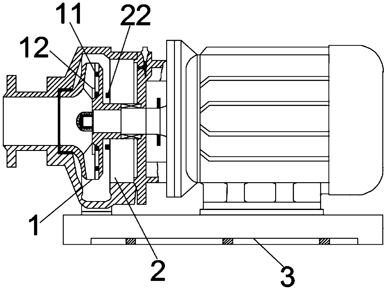
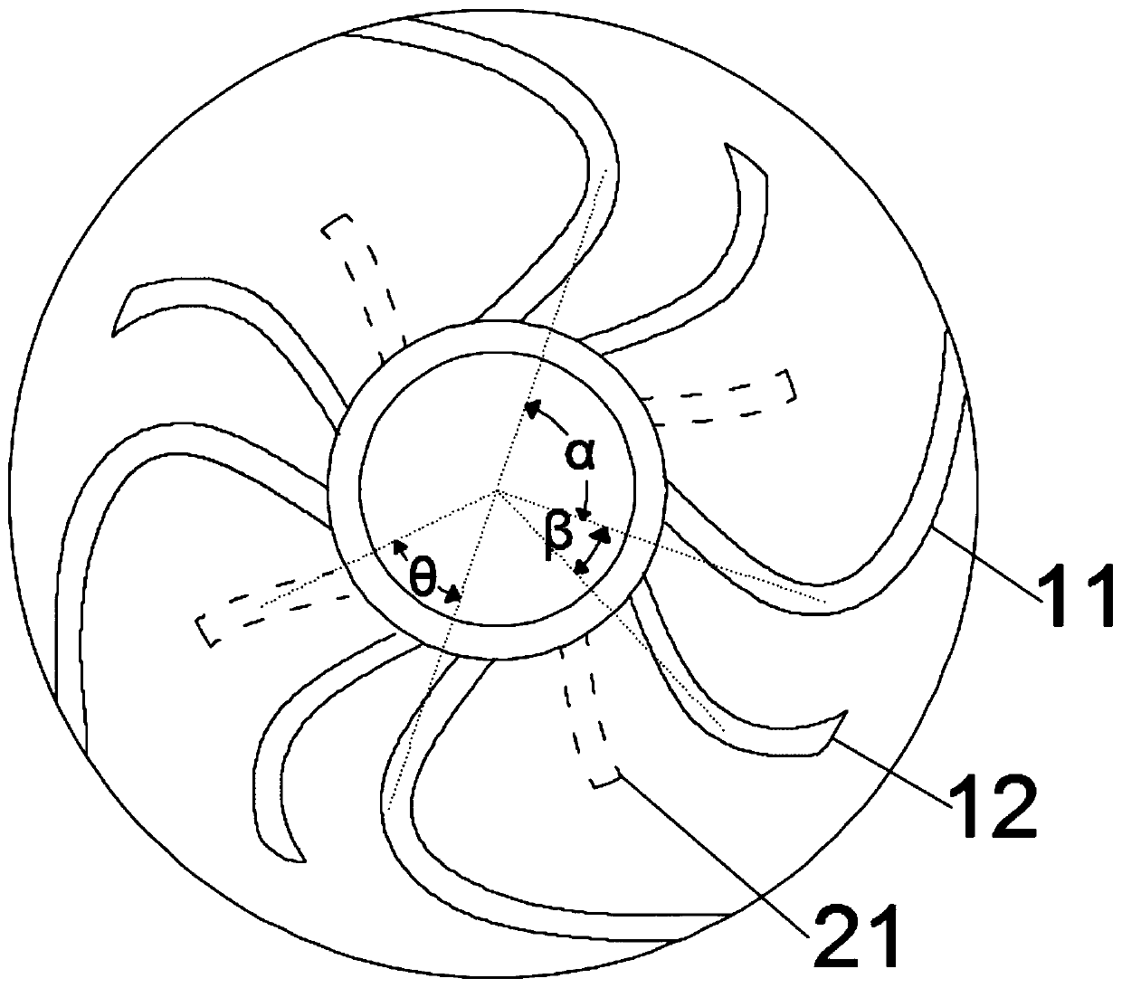
[0033]A centrifugal pump with an anti-cavitation impeller, including a pump body and a base, the pump body includes an impeller 1, an impeller front cover and an impeller rear cover 2, and the impeller 1 is fixedly connected between the impeller front cover and the impeller rear cover 2 Among them, the impeller 1 includes long blades 11 and short blades 12. The long blades 11 and short blades 12 are alternately designed to guide and limit the generation and development of the backflow vortex at the water inlet section, improve the flow instability in the flow channel of the impeller 1, and suppress The occurrence of cavitation reduces system pressure fluctuations and improves the operational stability of the centrifugal pump. The number of long blades 11 and short blades 12 is 4, and the angle between the backs of two adjacent long blades 11 is α, α =90 °, the angle between the back of the long blade 11 and the back of the adjacent short blade 12 is β, β=0.33α; the impeller rea...

Embodiment 2

[0035] A centrifugal pump with an anti-cavitation impeller, including a pump body and a base, the pump body includes an impeller 1, an impeller front cover and an impeller rear cover 2, and the impeller 1 is fixedly connected between the impeller front cover and the impeller rear cover 2 Among them, the impeller 1 includes long blades 11 and short blades 12. The long blades 11 and short blades 12 are alternately designed to guide and limit the generation and development of the backflow vortex at the water inlet section, improve the flow instability in the flow channel of the impeller 1, and suppress The occurrence of cavitation reduces system pressure fluctuations and improves the operational stability of the centrifugal pump. The number of long blades 11 and short blades 12 is 4, and the angle between the backs of two adjacent long blades 11 is α, α =90 °, the angle between the back of the long blade 11 and the back of the adjacent short blade 12 is β, β=0.35α; the impeller re...


PUM


Abstract

The invention relates to the technical field of centrifugal pumps, in particular to a centrifugal pump with a cavitation-resisting impeller. The pump comprises a pump body and a base; the pump body comprises the impeller, an impeller front cover plate and an impeller rear cover plate, the impeller is fixedly connected between the impeller front cover plate and the impeller rear cover plate, the impeller comprises long blades and short blades, the number of the long blades is N, the included angle between the back faces of two adjacent long blades is alpha and is equal to 360 / N, the included angles beta between the back faces of the long blades and the back faces of the adjacent short blades are larger than or equal to 0.33alpha and smaller than or equal to 0.35alpha, auxiliary blades arearranged on the impeller rear cover plate, the inner edges of the auxiliary blades are flush with the inner edges of the long blades, and the included angles between the auxiliary blades and the backfaces of the adjacent long blades are theta which is larger than or equal to 0.60 alpha and smaller than or equal to 0.66 alpha. Unstable flowing in an impeller runner can be avoided, the cavitation phenomenon is restrained, the system pressure fluctuation is reduced, the running stability of the pump is improved, dismounting and mounting are facilitated, and overhauling is facilitated.

Description

technical field [0001] The invention relates to the technical field of centrifugal pumps, in particular to a centrifugal pump with an anti-cavitation impeller. Background technique [0002] Centrifugal pump is a common hydraulic machine, which plays an important role in petrochemical, irrigation, aerospace and navigation. At present, a conventional operation method for improving the working efficiency of a centrifugal pump is to increase the specific rotational speed of the pump by increasing the rotational speed of the centrifugal pump. However, when the impeller is running at high speed, there will be a low-pressure area inside the impeller flow channel. When the pressure is lower than the saturated vapor pressure, the liquid inside the impeller flow channel will change into a vapor state, and the initial stage of cavitation will begin to appear and produce Lots of vacuoles. The generation and existence of cavitation inside the impeller will affect the hydraulic performa...

Claims


Application Information

Patent Timeline
Patent Type & Authority Applications(China)
IPC IPC(8): F04D29/22F04D29/24F04D29/66F04D29/00F04D29/62
CPCF04D29/007F04D29/2222F04D29/242F04D29/628F04D29/669
Inventor 张文宇罗永康
Owner ANHUI KANGYU HYDROPOWER MACHINERY COMPLETE EQUIP CO LTD
Learn More