
Centrifugal pumps with cavitation surge suppression

A centrifugal pump and cavitation technology, applied to pumps, parts of pumping devices for elastic fluids, pump components, etc., can solve problems such as vibration and noise, affecting the stable operation of the pump, and severe fluctuations in system flow and pressure. Achieve the effects of reducing vibration and noise, improving flow instability, and suppressing the generation of backflow vortices

Active Publication Date: 2020-11-06
CHINA AGRI UNIV
View PDF5 Cites 1 Cited by
  • Summary
  • Abstract
  • Description
  • Claims
  • Application Information

AI Technical Summary

Problems solved by technology

[0006] The purpose of the present invention is to provide a centrifugal pump that suppresses cavitation surge, alleviates the phenomenon of cavitation surge that is easy to occur in the inducer of the high-speed centrifugal pump in the prior art, and avoids the violent fluctuation of the system flow and pressure caused by the vibration and surge. Noise, a problem that seriously affects the stable operation of the pump

Method used


Image

  • Centrifugal pumps with cavitation surge suppression
  • Centrifugal pumps with cavitation surge suppression
  • Centrifugal pumps with cavitation surge suppression

Examples


Embodiment 1

[0078] According to the above description, this application provides a preferred embodiment.

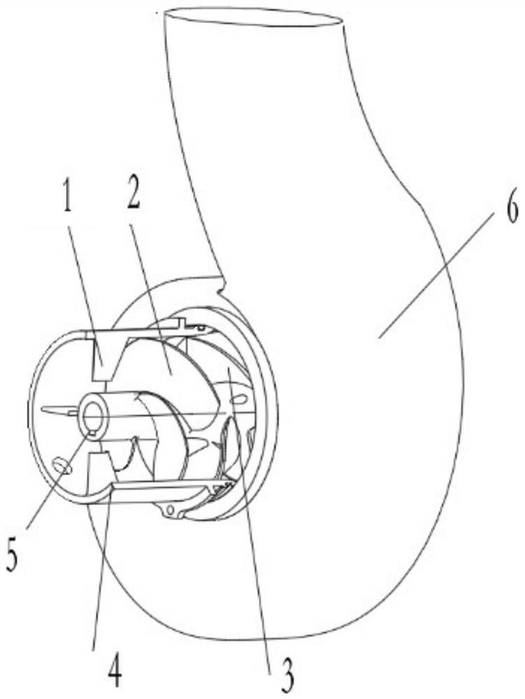
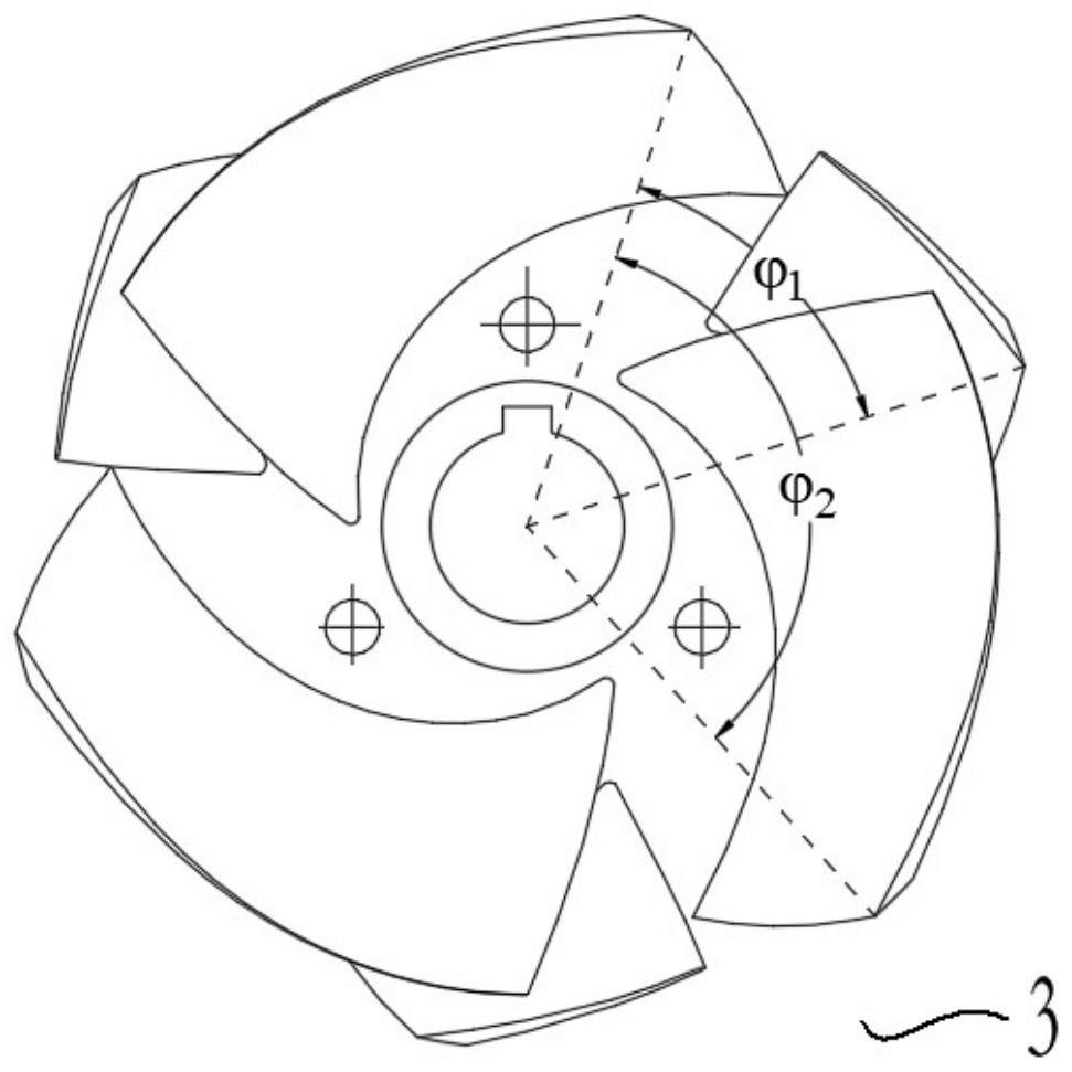
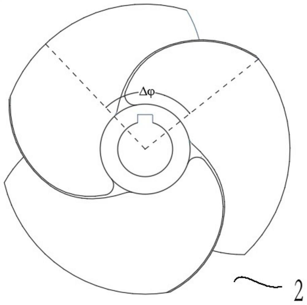
[0079] The number of long blades of the impeller 3 blades of the present embodiment is 3, and the angle between the backs of adjacent long blades The angle between the back of the long leaf and the back of the adjacent short leaf Sweep angle of inducer 2 is 130°, the design head of the inducer 2 is 5m, the number of rectifying plates 1 is 4, and the circumferential direction is evenly and symmetrically arranged; the thickness of the rectifying plate 1 is H 2 =1.6mm; the connection between the rectifying plate 1 and the water inlet section of the inducer 2 can be welded or integrally cast, and the side of the rectifying plate 1 and the connection between the rectifying plate 1 and the water inlet section of the inducer 2 are rounded, the size of the rounded corners is 0.8mm; the installation angle θ=0° between the rectifying plate 1 and the axis; the side of the rectifying plate ...


PUM


Abstract

The invention relates to the field of a centrifugal pump, and provides a centrifugal pump for suppressing cavitation surge. The centrifugal pump for suppressing the cavitation surge comprises a rectifying plate, an inducer, an impeller, a rim, and a hub, wherein the rectifying plate is fixed to the inner side of the rim and located at the entry end of the inducer, and the impeller islocated at theexit end of the inducer; the impeller comprises long-short compositeblades, and the adjacent blades distributed in the circumferential direction of the long-short compositebladesare not equidistantlydistributed. According to the centrifugal pump for suppressing the cavitation surge,through the design of the long-short compositeblades of the impeller, the inducer and the rectifying plate, the generation and development of reflow vortexes at the inlet and the water inlet section of the inducer are well guided and limited,the generation and development of the reflow vortex insidea high-speed pump flow passageare well suppressed, the unstable flow inside the flow passage is relieved, the occurrence of the cavitation surge is suppressed, the pressure surge of a system is reduced, the vibration and noise during operating of the high-speed centrifugal pump is improved, andthe operational stability of the centrifugal pump is improved.

Description

technical field [0001] The invention relates to the field of centrifugal pumps, in particular to a centrifugal pump capable of suppressing cavitation surge. Background technique [0002] High-speed centrifugal pumps are widely used in petrochemical, aerospace and other fields. Due to the high speed and low flow rate of high-speed centrifugal pumps, cavitation is easy to occur at the pump inlet, and cavitation surge occurs under low flow conditions. Therefore, Ensuring the long-term safe and stable operation of high-speed pumps is the key to hydraulic design. [0003] At present, installing an inducer in a high-speed centrifugal pump has become a key technology to ensure that the pump obtains superior cavitation performance. When the inducer is used in a high-speed centrifugal pump, its working conditions often change during operation, and it is often accompanied by complex cavitation phenomena. Complex; when cavitation occurs in the inducer during operation, it is easy to ...

Claims


Application Information

Patent Timeline
Patent Type & Authority Patents(China)
IPC IPC(8): F04D29/66F04D29/22
CPCF04D29/225F04D29/2272F04D29/669
Inventor 肖若富吕亚飞姚志峰杨魏魏志聪
Owner CHINA AGRI UNIV
Learn More