Shock absorber with locking type vehicle-used hydraulic jacking rod

A technology of hydraulic ejector rod and shock absorber, which is applied in the direction of shock absorber, liquid shock absorber, spring/shock absorber, etc., and can solve the problem of accelerated seal ring wear and other problems

Pending Publication Date: 2019-12-13
ZHEJIANG JINBO SHOCK ABSORBER MFG
View PDF0 Cites 0 Cited by
  • Summary
  • Abstract
  • Description
  • Claims
  • Application Information

AI Technical Summary

Problems solved by technology

[0002] In the shock absorber in the prior art, the cylinder is filled with damping oil. When the piston is pressed and slides with the ejector rod, under the push of the piston, the damping oil at the rear end of the cylinder will cause resistance to the feeding of the piston. In this process, due to the change of the position of the piston in the cylinder, the hydraulic pressure of the front and rear sections of the piston in the cylinder also changes, and the hydraulic pressure of the rear section is significantly greater than that of the front section. Therefore, after the external vibration force is eliminated, the piston is reset under the combined action of the return spring and the hydraulic pressure difference. However, due to the large hydraulic pressure difference on both sides of the piston, the piston and the inner wall of the cylinder are usually sealed. This makes the high-pressure side always have a tendency to input damping oil and thrust toward the low-pressure side through the gap between the piston and the inner wall of the cylinder. This thrust will cause great pressure on the sealing ring and accelerate the wear of the sealing ring.

Method used


Image

  • Shock absorber with locking type vehicle-used hydraulic jacking rod
  • Shock absorber with locking type vehicle-used hydraulic jacking rod

Examples


Embodiment Construction

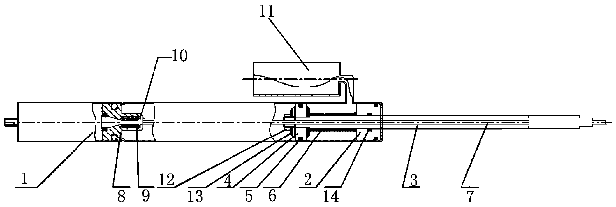
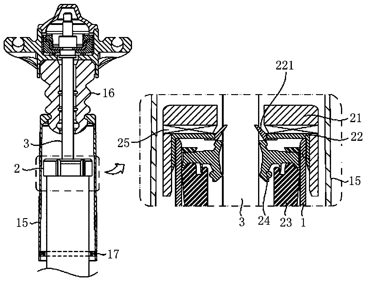
[0013] The shock absorber with locking type vehicle hydraulic jack in the present invention will be further described with reference to the accompanying drawings.

[0014] As shown in the drawings, this embodiment is a shock absorber with a lock-type vehicle hydraulic jack, including a cylindrical working cylinder 1, the inside of the working cylinder is hollow to form a cavity, and the rear of the working cylinder end seal, the front end cover of the working cylinder is provided with a guide 2, and the cavity is sealed by the guide, and a through hole is formed in the center of the guide, and the through hole communicates with the cavity. A push rod 3 is plugged into the through hole, the front end of the push rod extends outside the working cylinder, and the rear end of the push rod is inserted into the cavity, and the whole push rod can be subjected to an external impact force. After the action, it is reciprocatingly fed along the axial direction of the working cylinder. A ...


PUM


Abstract

The invention discloses a shock absorber with a locking type vehicle-used hydraulic jacking rod. The shock absorber with the locking type vehicle-used hydraulic jacking rod comprises a barrel-shaped working cylinder. The working cylinder is hollow inside and a cavity is formed inside the working cylinder. The rear end of the working cylinder is sealed. A guide apparatus is arranged at the front end of the working cylinder in a covering manner. The cavity is sealed by the guide apparatus. A through hole is formed in the center of the guide apparatus. The jacking rod is connected to the throughhole in an inserted manner. A piston is arranged in the portion, located in the cavity, of the jacking rod in a sleeving manner. A resetting auxiliary spring is arranged between the piston and the guide apparatus. The resetting auxiliary spring is also arranged on the jacking rod in a sleeving manner. A sealing push rod is arranged in the jacking rod. The front end of the sealing push rod is fixedto the jacking rod. The rear end of the sealing push rod penetrates through the rear end of the jacking rod and extends to the cavity. A floating piston is fixed to the rear end of the sealing push rod. An oil storage barrel is fixed to the side wall of the front end of the working cylinder. Damping oil stored in the oil storage barrel can flow into the cavity.

Description

technical field [0001] The invention mainly relates to the technical field of shock absorbers, in particular to a shock absorber with a lock-type vehicle hydraulic push rod. Background technique [0002] In the shock absorber in the prior art, the cylinder is filled with damping oil. When the piston is pressed and slides with the ejector rod, under the push of the piston, the damping oil at the rear end of the cylinder will cause resistance to the feeding of the piston. In this process, due to the change of the position of the piston in the cylinder, the hydraulic pressure of the front and rear sections of the piston in the cylinder also changes, and the hydraulic pressure of the rear section is significantly greater than that of the front section. Therefore, after the external vibration force is eliminated, the piston is reset under the combined action of the return spring and the hydraulic pressure difference. However, due to the large hydraulic pressure difference on both...

Claims


Application Information

Patent Timeline
IPC IPC(8): F16F9/19F16F9/36F16F9/34F16F9/32
CPCF16F9/19F16F9/3207F16F9/3214F16F9/34F16F9/36
Inventor 柳平波王海勇
Owner ZHEJIANG JINBO SHOCK ABSORBER MFG
Why Eureka
Try Eureka