
Kiln with water cooling structure

A water-cooling and kiln technology, applied in furnaces, furnace cooling, furnace components, etc., can solve the problems of low reliability of heat exchangers, poor fluidity of cooling water, and low heat exchange efficiency, so as to prevent water leakage in the furnace body and eliminate The risk of water leakage, the effect of stable and reliable structure

Inactive Publication Date: 2019-12-13
48TH RES INST OF CHINA ELECTRONICS TECH GROUP CORP
View PDF5 Cites 0 Cited by
  • Summary
  • Abstract
  • Description
  • Claims
  • Application Information

AI Technical Summary

Problems solved by technology

[0003] (1) The existing jacket water-cooling structure is mainly to cool the furnace by setting a cooling water interlayer around the furnace. Due to the poor fluidity of the cooling water in the interlayer, the heat exchange efficiency is not high, the cooling effect is not good, and the product is released. The kiln temperature often does not meet the requirements
[0004] (2) The existing water-cooling structure of heat exchange tubes is usually in the form of an integral heat exchanger. The heat in the furnace is absorbed by the heat exchanger to reduce the temperature in the furnace. Since the cooling water in the heat exchanger has a strong fluidity, it is The jacketed water-cooled structure has better heat transfer performance, but the temperature in the front section of the kiln cooling zone generally reaches about 800°C, and the heat exchanger is usually formed by welding multiple heat exchange tubes to form a whole. Cracks may occur, so the reliability of the integral heat exchanger is often not high, and once a single heat exchange tube is damaged, it must be replaced as a whole, and the maintenance cost is high

Method used


Image

  • Kiln with water cooling structure
  • Kiln with water cooling structure

Examples


Embodiment Construction

[0024] The present invention will be described in further detail below in conjunction with the accompanying drawings and specific embodiments.

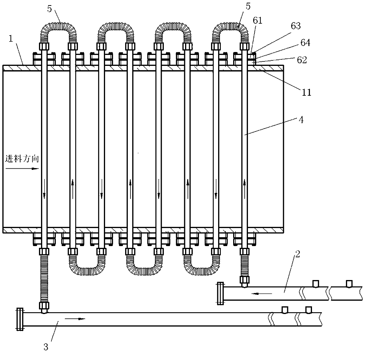
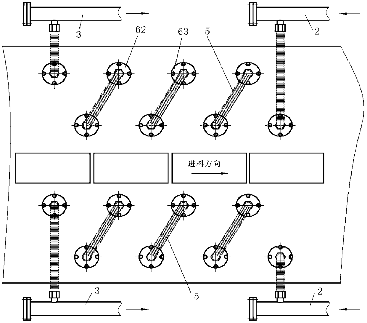
[0025] Such as figure 1 with figure 2 As shown, the kiln with a water-cooled structure in this embodiment includes a furnace body 1 and a water-cooled structure. The water-cooled structure includes a water inlet pipe 2, an outlet pipe 3 and a plurality of water-cooled pipes 4. Each water-cooled pipe 4 runs through the furnace body 1. And the two ends extend to the outside of the furnace wall 11, a plurality of water-cooled pipes 4 are connected in series through the joint pipe 5, the water-cooled pipe 4 at the head end is connected with the water inlet pipe 2, and the water-cooled pipe 4 at the tail end is connected with the water outlet pipe 3, so that the cooling water Enter from the water inlet pipe 2, flow along the water-cooled pipe 4 at the head end, pass through each water-cooled pipe 4 in the middle, reach the water-cooled p...


PUM


Abstract

The invention discloses a kiln with a water cooling structure. A kiln body and the water cooling structure are included. The water cooling structure comprises a water inlet pipe, a water outlet pipe and a plurality of water cooling pipes. The water cooling pipes penetrate through the kiln body, and the two ends of each water cooling pipe extend to the outer side of the kiln wall. The multiple water cooling pipes are connected in series in an end-to-end manner through connector pipes. The water cooling pipe at the head end is connected with the water inlet pipe, and the water cooling pipe at the tail end is connected with the water outlet pipe. The single water cooling pipes are strung to form a structure similar to a coil pipe heat exchanger. No connectors exist for the water cooling pipesin the kiln body, the adjacent water cooling pipes are connected through the connector pipes at the outer portion of the kiln body, pipeline connecting points are arranged outside the kiln body, therisk of water leakage in the kiln body is eliminated, and the structure is reliable. Compared with an integral heat exchanger, the structure is more flexible, a user can flexibly change the connectingmethod and the number of the water cooling pipes according to the actual cooling need, accordingly, the highest cooling efficiency is achieved, after the single water cooling pipes are damaged, independent replacement can be conducted, normal work of other water cooling pipes cannot be influenced, and the maintenance cost is greatly reduced.

Description

technical field [0001] The invention relates to sintering equipment, in particular to a kiln with water cooling structure. Background technique [0002] Kilns are widely used in the firing of various industrial materials. The main process of products in the kiln is preheating-firing-cooling. Among them, the product exit temperature is an important technical index of the roller kiln. If the exit temperature is too high, the product will not only have the risk of being oxidized, but also is not conducive to the subsequent loading and unloading. The existing water cooling structures for kilns mainly include jacket water cooling and heat exchange tube water cooling. [0003] (1) The existing jacket water-cooling structure is mainly to cool the furnace by setting a cooling water interlayer around the furnace. Due to the poor fluidity of the cooling water in the interlayer, the heat exchange efficiency is not high, the cooling effect is not good, and the product is released. The...

Claims


Application Information

Patent Timeline
Patent Type & Authority Applications(China)
IPC IPC(8): F27D9/00
CPCF27D9/00F27D2009/0013F27D2009/0024
Inventor 凌俊刘金平
Owner 48TH RES INST OF CHINA ELECTRONICS TECH GROUP CORP
Learn More