
Blasting fixing device and system and method for dredging and plugging of wells using it

A technology of fixing device and sliding well, which is applied in the field of sliding well dredging system and blasting fixing device, can solve the problems of difficult operation and high cost

Active Publication Date: 2020-10-20
CENT SOUTH UNIV
View PDF6 Cites 0 Cited by
  • Summary
  • Abstract
  • Description
  • Claims
  • Application Information

AI Technical Summary

Problems solved by technology

[0005] The technical problem to be solved by the present invention is to provide a blasting fixing device and its application for the blasting of the chute blockage and its application in view of the problems of difficult operation and high cost in the existing blasting dredging means used in the mine dredging Unblocking systems and methods

Method used


Image

  • Blasting fixing device and system and method for dredging and plugging of wells using it
  • Blasting fixing device and system and method for dredging and plugging of wells using it
  • Blasting fixing device and system and method for dredging and plugging of wells using it

Examples


Embodiment 1

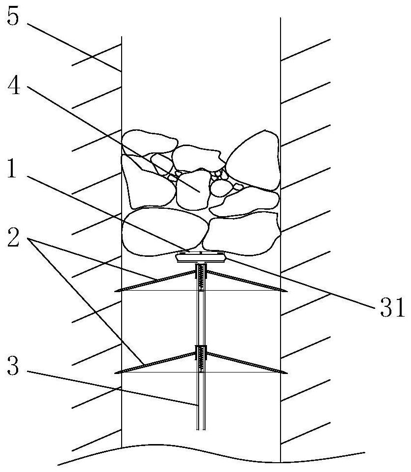
[0040] see figure 1 , the blasting fixing device in the illustration is a specific embodiment of the present invention, which can be used for fixing the explosive package when blasting and clearing the blockage inside the chute channel, and can also be used for fixing the explosive package when blasting inside other channels.

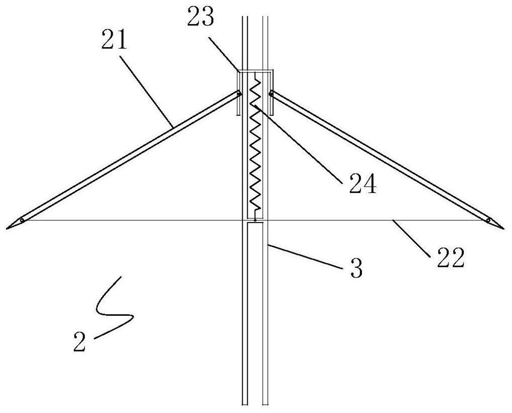
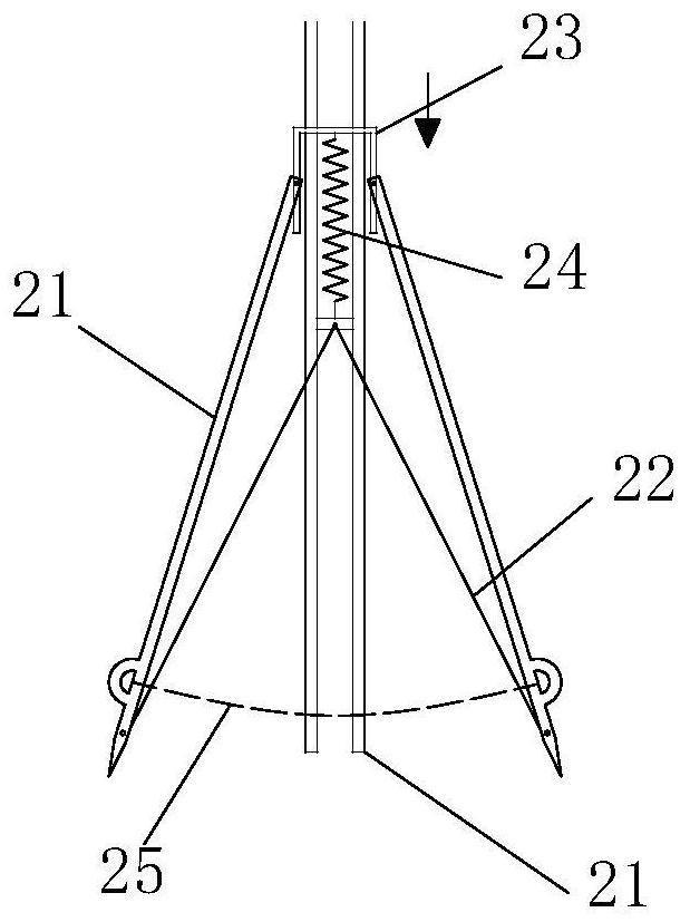
[0041] The blasting fixture of this embodiment includes an umbrella-shaped support mechanism 2 and a vertical pole 3, wherein the vertical pole 3 is the axis skeleton of the entire blasting fixture, and the top of the vertical pole 3 is provided with a support platform 31 for placing the explosive package 1. The support mechanism 2 is set on the vertical pole 3, and the explosive package 1 is arranged on the top of the entire blasting fixture. After the explosive package 1 is attached to the blockage 4 to be blasted, the umbrella-shaped support mechanism 2 that forms a forward conical support structure The entire blasting fixture and the explosive packa...

Embodiment 2

[0049] see Figure 5 The chute dredging system disclosed in this example is a further application implementation of the blasting fixture in Example 1. On the basis of the blasting fixture in Example 1, this example further provides a blasting fixture and an explosive The package is moved and transported to the lifting device 6 at the high-level blockage in the vertical chute, the entire blasting fixture is placed on the lifting device 6, and the lifting device 6 is set on the downcomer 51 below the blockage in the chute through the telescopic bottom plate 61 that stretches in the horizontal direction Inside, the telescopic bottom plate 61 can be extended and retracted through guide rails and electric telescopic rods or hydraulic telescopic rods. The extended telescopic bottom plate 61 extends the lifting device 6 and the blasting fixing device placed on it from the downcomer 51 to the chute 52. internal.

[0050] see in conjunction Image 6 , the lifting device 6 in the pres...

Embodiment 3

[0053] Considering the irregularity of the inner wall of the mine channel, all the diagonal struts 21 in the umbrella support mechanism of the blasting fixture may not be able to fully support the inner wall of the channel. This embodiment provides another specific implementation of the blasting fixture to fix the problem.

[0054] see in conjunction figure 1 as well as Figure 7 with Figure 8 , the ends of the diagonal struts 21 of the umbrella support mechanism 2 in the present embodiment are fixed and hinged on the independent sliders 26, and one diagonal strut 21 corresponds to one slider 26, and the vertical rod 3 is provided along the axial direction for The sliding block 26 is an annular slideway for axial sliding, and several groups of corresponding diagonal struts 21 are arranged on the outer circumference of the vertical rod 3 to connect the sliding grooves 33 of the sliding blocks 26, and all the sliding blocks 26 connected to the diagonal struts 21 pass through ...


PUM


Abstract

The invention discloses a blasting fixing device, and a draw shaft dredging system and method applied to the blasting fixing device. The blasting fixing device comprises a vertical pole and one or more sets of umbrella-shaped support mechanisms arranged on the vertical pole, a support platform used for fixing blasting charges is arranged at the top of the vertical pole, the umbrella-shaped supportmechanisms comprise a plurality of inclined brace rods arranged in an umbrella shape around the vertical pole, the umbrella-shaped support mechanisms are in opening states, one ends of the inclined brace rods are connected to the vertical pole, and the other ends abut against and are supported on the inner wall of a blasting channel through the blasting charges and gravity of the dead weight of the device. According to the blasting fixing device, the umbrella-shaped support mechanisms are used for fixing the blasting charges, after the blasting charges are transported below the position of ablockage, single support structures of the umbrella-shaped support mechanisms are used for supporting and fixing the blasting charges in a draw shaft for blasting for dredging, according to the draw shaft dredging system and method, the explosive transportation process is more stable, the blasting method is more destructive, at the same time, only the inexpensive umbrella-shaped support mechanismsare damaged during the initiation process, and the cost is lower.

Description

technical field [0001] The invention belongs to the mine blasting technology, and in particular relates to a blasting fixing device and a system and method for unclogging a shaft for its application. Background technique [0002] Mine usually excavate a series of shafts between the main hoist system and the working level to realize the transfer of ore and waste rock in the ore development system. However, during the transfer of ore and waste rock, the movement speed of large rock blocks is slowed down under the action of the rough wall of the chute, and then they are blocked in the chute, and small rock blocks are covered on it and gradually compacted and piled up, eventually forming slag in the chute Abnormal phenomena such as blockage and arching. The abnormal state of the shaft posed a great threat to the normal production of the mine and the operation of the mine staff. In this case, the mine must take appropriate measures to dredge the chute to ensure the normal produ...

Claims


Application Information

Patent Timeline
Patent Type & Authority Patents(China)
IPC IPC(8): F42D1/00F42D3/04
CPCF42D1/00F42D3/04
Inventor 史秀志喻智陈新霍晓锋张军辉张宗国苟永刚饶帝军张世安
Owner CENT SOUTH UNIV
Learn More