Optical fiber displacement sensor and measuring method thereof

A technology of displacement sensor and optical fiber sensor, which is applied in the field of sensors, can solve the problems of large size and achieve the effects of small size, cost saving and long signal transmission distance

Active Publication Date: 2019-12-13
CENT SOUTH UNIV
View PDF7 Cites 5 Cited by
  • Summary
  • Abstract
  • Description
  • Claims
  • Application Information

AI Technical Summary

Problems solved by technology

At present, the mainstream optical fiber displacement sensors all have the problem of large volume. Therefore, it is of great significance to study a small volume and high sensitivity optical fiber displacement sensor.

Method used


Image

  • Optical fiber displacement sensor and measuring method thereof
  • Optical fiber displacement sensor and measuring method thereof
  • Optical fiber displacement sensor and measuring method thereof

Examples


Embodiment Construction

[0042] The specific implementation manners of the present invention will be further described in detail below in conjunction with the accompanying drawings and embodiments. The following examples are used to illustrate the present invention, but are not intended to limit the scope of the present invention.

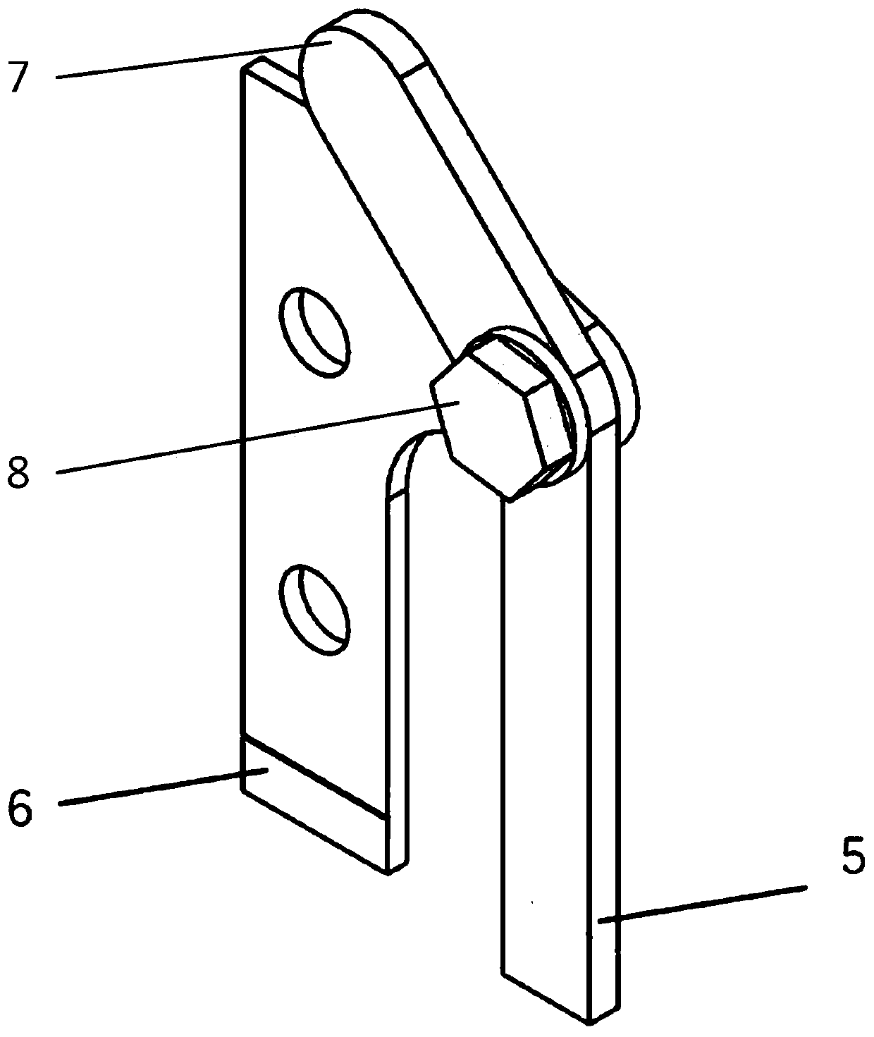
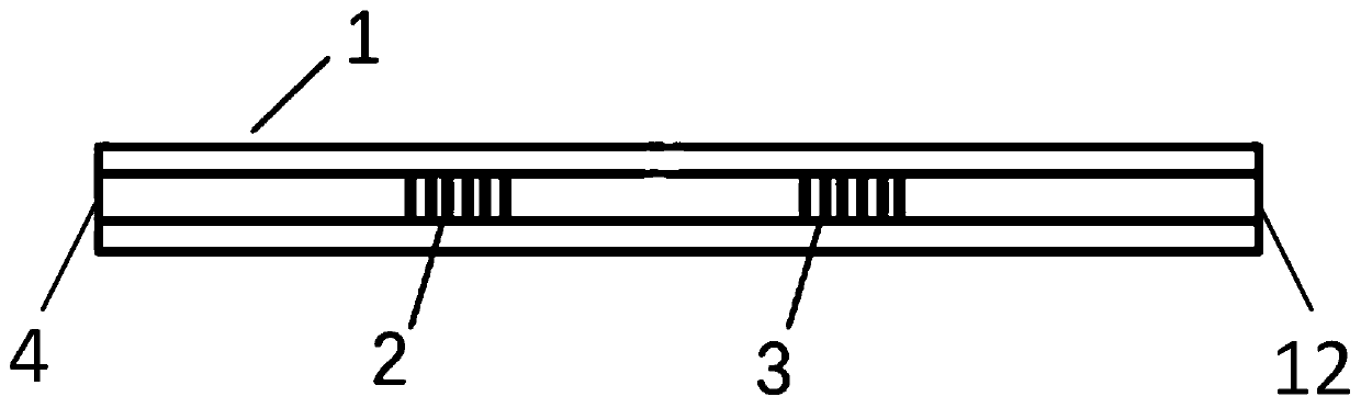
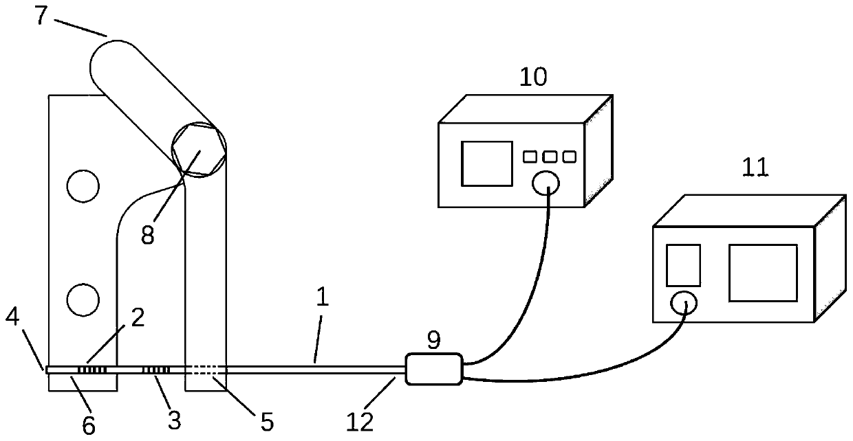
[0043] The invention provides an optical fiber displacement sensor, such as figure 1 As shown, it includes a substrate and an optical fiber sensor; the substrate includes a fixing plate, a turning plate and a connector 8, the fixing plate has three through holes and an optical fiber groove-5, and the turning plate is divided into an upper corner by a through hole at a corner The lower turning plate is parallel to the fixed plate, and the direction of the corner towards the fixed plate is an obtuse angle, and the angle of the obtuse angle is greater than or equal to 110°. The connecting piece 8 connects the The fixing plate is connected with the turning plate, the other tw...


PUM


Abstract

The invention discloses an optical fiber displacement sensor and a measuring method thereof. The optical fiber displacement sensor comprises a substrate and an optical fiber sensor; the substrate comprises a fixed plate, a turning plate and a connecting piece; a lower turning plate part is parallel to the fixed plate, a corner is of an obtuse angle in the direction facing the fixed plate, and thefixed plate is connected with the turning plate by the connecting piece through a through hole of the fixed plate and a through hole of the turning plate; a first optical fiber groove and a second optical fiber groove are staggered in parallel, located in the sizes, facing each other, of the fixed plate and the lower turning plate part respectively, and used for fixing the optical fiber sensor; the top end of an upper turning plate part serves as a contact end making contact with a measured object; and the optical fiber sensor comprises an optical fiber, and a first Bragg grating and a secondBragg grating which are etched on a fiber core of the optical fiber. Displacement of the measured object is amplified through the substrate and converted into axial tension to the first Bragg grating.The optical fiber displacement sensor has the advantages of being small in size, free of electromagnetic interference, long in signal transmission distance and high in measurement precision.

Description

technical field [0001] The invention relates to the technical field of sensors, in particular to an optical fiber displacement sensor and a measuring method thereof. Background technique [0002] Displacement measurements are an important monitoring metric for assessing the health of structures in many fields, including civil, industrial, and aerospace engineering. The current mainstream displacement sensors are based on electronic sensing technology, such as capacitive and magnetoresistive displacement sensors. However, displacement sensors based on electronic sensing technology have low long-term stability, poor durability, and are susceptible to high-intensity electromagnetic interference. Displacement sensors based on fiber Bragg gratings have the advantages of anti-electromagnetic interference, corrosion resistance, and the ability to accommodate multiple measuring points in one fiber, and have attracted widespread attention in recent years. At present, some optical f...

Claims


Application Information

Patent Timeline
Patent Type & Authority Applications(China)
IPC IPC(8): G01B11/02G01D5/353
CPCG01B11/02G01D5/35316
Inventor 孙小燕曾理胡友旺段吉安
Owner CENT SOUTH UNIV
Why Eureka
Try Eureka