
Underwater soil body settlement monitoring system and monitoring method

A settlement monitoring and soil technology, applied in height/level measurement, measuring device, surveying and mapping and navigation, etc., can solve problems such as difficulty in meeting tunnel construction control requirements, inability to timely feedback construction work surfaces, and difficulty for construction personnel to correct deviations.

Pending Publication Date: 2019-12-13
BEIJING NO 4 MUNICIPAL CONSTR ENG +1
View PDF0 Cites 0 Cited by
  • Summary
  • Abstract
  • Description
  • Claims
  • Application Information

AI Technical Summary

Problems solved by technology

[0004] The existing technology has the following defects: First, there are large errors during underwater construction, with an accuracy of 100mm, which cannot provide accurate monitoring data for construction personnel, and it is difficult to meet the control requirements of tunnel construction for settlement; second , the analysis of underwater scanning data is slow, and the settlement data can only be obtained after 1 to 2 hours, which cannot be fed back to the construction work surface in time. It is difficult for construction personnel to correct deviations in time, and the real-time performance is poor.

Method used


Image

  • Underwater soil body settlement monitoring system and monitoring method
  • Underwater soil body settlement monitoring system and monitoring method
  • Underwater soil body settlement monitoring system and monitoring method

Examples


Embodiment 1

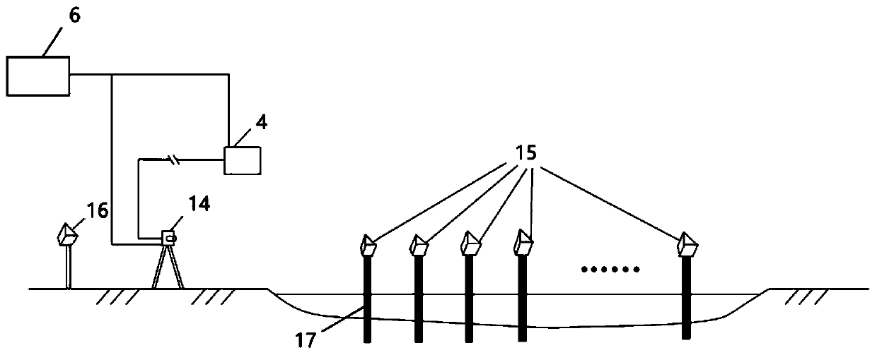
[0024] figure 1 It is a schematic diagram of an underwater soil settlement monitoring system provided in Embodiment 1 of the present invention. This embodiment is applicable to the real-time acquisition of the trend of the soil below the water bottom in the construction of trenchless tunnels. The underwater soil settlement monitoring system includes: a measuring instrument 1, a target target 2, a rear-view target 3, and a host computer 4 and supporting structures5.

[0025] Measuring instrument 1 is communicated with host computer 4, and is used to send a first light signal to target target 2, receive the first reflected light signal reflected by target target 2, send a second light signal to rear-view target 3, receive The second reflected light signal reflected by the rear-view target 3 sends the current data information to the upper computer 4 according to the received first reflected light signal and the second reflected light signal.

[0026] The upper computer 4 is use...

Embodiment 2

[0032] figure 2 It is a schematic diagram of an underwater soil subsidence monitoring system provided in Embodiment 2 of the present invention. The technical solution of this embodiment is further refined on the basis of the above-mentioned technical solution. The underwater soil settlement monitoring system includes: a measuring instrument 1 , a target target 2 , a backsight target 3 , a host computer 4 and a support structure 5 . Wherein, the surveying instrument 1 is an automated total station 14 , the target target 2 is a reflecting prism 15 , the backsight target 3 is a backsight prism 16 , and the supporting structure 5 is a steel pipe 17 .

[0033] The automated total station 14 communicates with the upper computer 4, and is used to send the first light signal to the reflective prism 15, receive the first reflected light signal reflected by the reflective prism 15, send the second light signal to the rear-view prism 16, and receive the rear-view light signal. The seco...

Embodiment 3

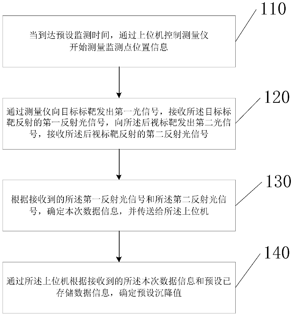
[0041] image 3 It is a flow chart of a method for monitoring underwater soil subsidence provided by Embodiment 3 of the present invention. This embodiment can be applied to the construction of trenchless tunnels to obtain real-time changes in the trend of soil below the water bottom. This method can be implemented by the above-mentioned technology The underwater soil subsidence monitoring system in the scheme is implemented, which specifically includes the following steps:

[0042] Step 110, when the preset monitoring time is reached, the host computer 4 controls the measuring instrument 1 to start measuring the position information of the monitoring point.

[0043] Wherein, the preset monitoring time is set in advance by the host computer 4 before the measuring instrument 1 starts to measure the monitoring point information;

[0044] The monitoring time may be periodic, and the specific period may be determined according to the number of points to be monitored. For example...


PUM

PropertyMeasurementUnit
Diameteraaaaaaaaaa

Abstract

The embodiments of the invention disclose an underwater soil body settlement monitoring system and monitoring method. The system comprises a measuring instrument, a target, a rearview target, an uppercomputer and a supporting structure; the measuring instrument is in communication connection with the upper computer and is used for emitting first optical signals to the target, receiving first reflected optical signal reflected by the target, emitting second optical signals to the rearview target, receiving second reflected optical signals reflected by the rearview target, sending current datainformation to the upper computer according to the received first reflected optical signals and second reflected optical signals; the target is fixedly arranged at the top end of the supporting structure; and the supporting structure is fixed at the bottom of to-be-monitored water. According to the underwater soil body settlement monitoring system and monitoring method provided by the embodimentsof the invention, the supporting structure is used for reflecting underwater settlement to a water surface; an automatic monitoring system is used for monitoring; and therefore, the problems of low precision and low real-time performance in a construction process are solved, the real-time feedback of underwater soil settlement is realized, construction parameters can be conveniently adjusted in time, and the precision level of monitoring data can be improved.

Description

technical field [0001] The embodiments of the present invention relate to tunnel engineering construction technology, in particular to a monitoring system and method for underwater soil settlement. Background technique [0002] When the tunnel crosses the river and crosses the bottom of the water, due to the disturbance of the soil caused by the construction, the bottom of the water will subside, which will increase the difficulty of operation for the construction personnel. [0003] Generally, land subsidence is directly monitored with a precision level, but the complexity of the underwater soil makes this method difficult to implement. The commonly used underwater monitoring method is the underwater scanning technology, which uses ultrasonic scanning to scan the changing trend of the underwater. When monitoring, the ultrasonic transducer is placed at a certain position underwater. The measurement and control device controls the ultrasonic transducer to send out sound wave ...

Claims


Application Information

Patent Timeline
IPC IPC(8): G01C5/00
CPCG01C5/00
Inventor 周政刁春仁张海鹰郑仔弟吴钦刚耿富林岳爱敏王京磊聂晓彦
Owner BEIJING NO 4 MUNICIPAL CONSTR ENG
Learn More