
Vehicle positioning optimization method, device, equipment and storage medium

A technology of vehicle positioning and optimization method, applied in the field of data processing, can solve the problems that the positioning information cannot accurately control the driving of the vehicle, cannot meet the positioning requirements of automatic driving vehicles, and the positioning accuracy of the positioning system is low, so as to meet the positioning requirements, improve the accuracy, Solve for fast effects

Active Publication Date: 2019-12-13
BEIJING BAIDU NETCOM SCI & TECH CO LTD
View PDF4 Cites 14 Cited by
  • Summary
  • Abstract
  • Description
  • Claims
  • Application Information

AI Technical Summary

Problems solved by technology

[0005] Embodiments of the present application provide an optimization method, device, equipment, and storage medium for vehicle positioning, which solves the problem that the positioning accuracy of the positioning system in the prior art is low, and thus cannot meet the positioning requirements of self-driving vehicles, and according to the low positioning accuracy The technical problem that the positioning information cannot accurately control the vehicle to drive along the planned route

Method used


Image

  • Vehicle positioning optimization method, device, equipment and storage medium
  • Vehicle positioning optimization method, device, equipment and storage medium
  • Vehicle positioning optimization method, device, equipment and storage medium

Examples


Embodiment 1

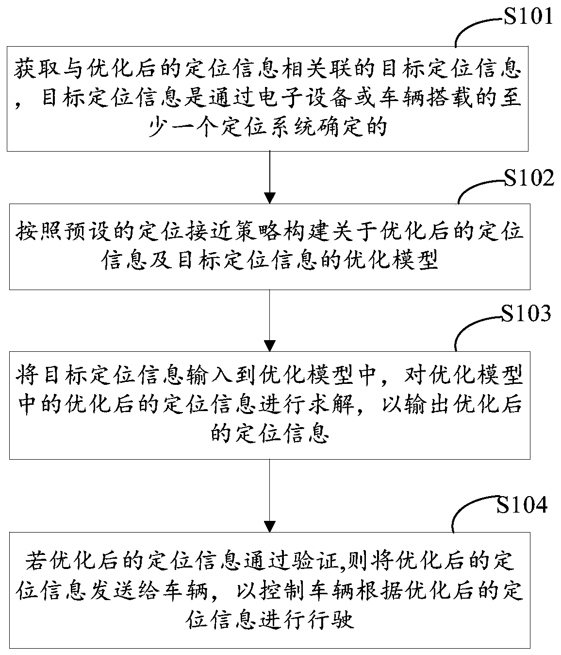
[0089] figure 2 is a schematic flowchart of an optimization method for vehicle positioning provided according to the first embodiment of the present application, as shown in figure 2 As shown, the execution subject of the embodiment of the present application is a vehicle positioning optimization apparatus, and the vehicle positioning optimization apparatus may be integrated into an electronic device. Then, the optimization method for vehicle positioning provided in this embodiment includes the following steps.

[0090] Step 101: Obtain target positioning information associated with the optimized positioning information, where the target positioning information is determined by at least one positioning system mounted on an electronic device or a vehicle.

[0091] In this embodiment, the target positioning information is the optimized positioning information. If the optimized positioning information is the optimized vehicle pose, the target positioning information may inclu...

Embodiment 2

[0111] image 3 is a schematic flow chart of the vehicle positioning optimization method provided according to the second embodiment of the present application, as shown in image 3 As shown, the vehicle positioning optimization method provided in this embodiment is based on the vehicle positioning optimization method provided in Embodiment 1 of the present application, and further refines steps 101-104. And it also includes the step of verifying the perceived lane lines and the step of processing the high-precision map lane lines, so the vehicle positioning optimization method provided by this embodiment includes the following steps.

[0112] Step 201: Obtain at least one confidence characteristic information of the perceived lane line determined by the perception positioning system, verify the perceived lane line according to the confidence characteristic information, and repair or delete the perceived lane line if the perceived lane line fails the verification.

[0113] Fu...

Embodiment 3

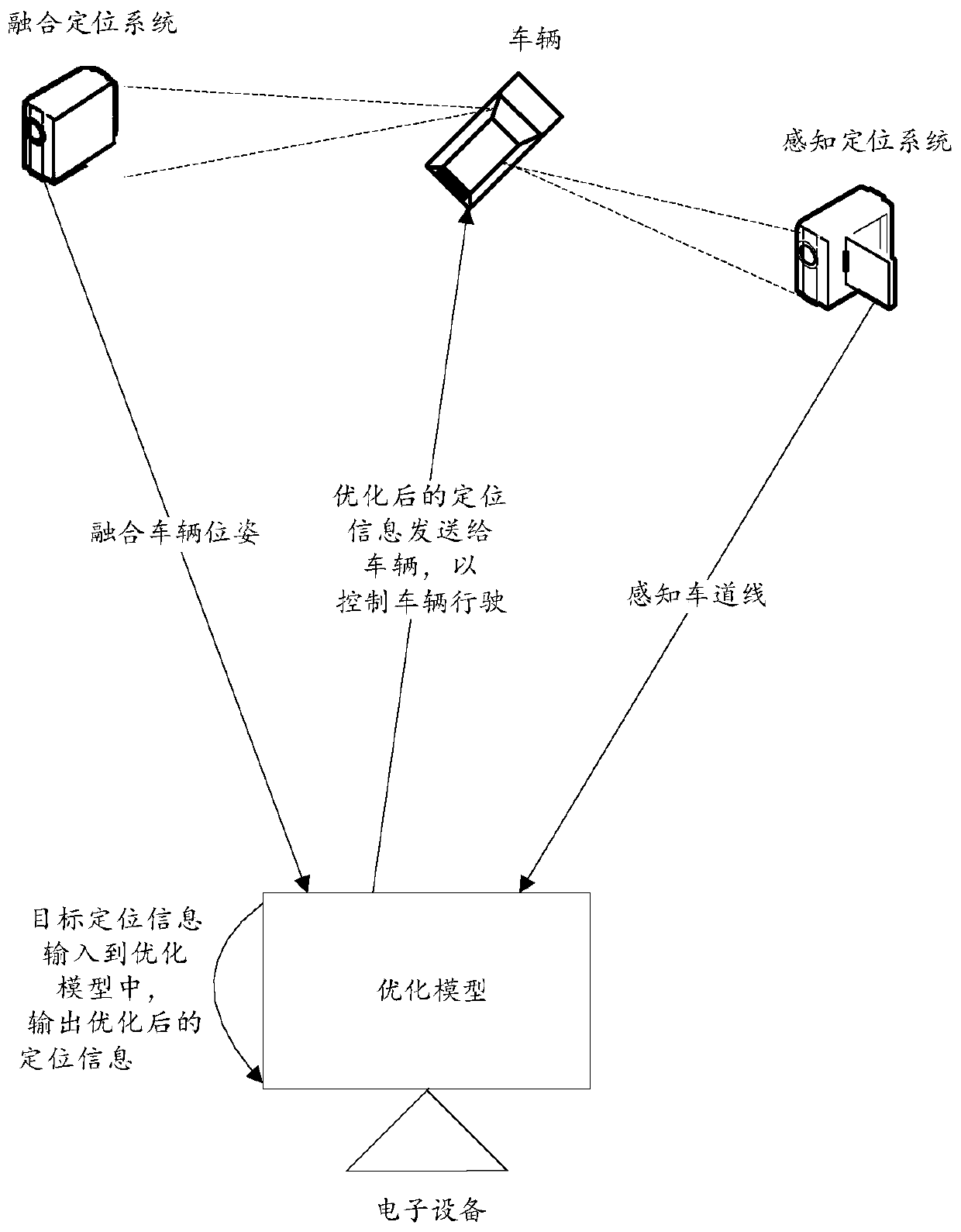
[0255] Figure 9 A schematic diagram of the signaling flow of the optimization method for vehicle positioning provided according to the third embodiment of the present application, such as Figure 9 As shown, the optimization method for vehicle positioning provided by this embodiment includes the following steps:

[0256] Step 301, the fusion positioning system obtains the fusion vehicle pose.

[0257] Step 302, the fusion positioning system sends the fusion vehicle pose to the electronic device

[0258] Step 303, the perception and positioning system acquires the perception lane line.

[0259] Step 304, the sensing and positioning system sends the sensing lane line to the electronic device.

[0260] Step 305, the electronic device obtains the lane lines of the high-precision map and the historically optimized vehicle pose, and obtains the fused vehicle pose associated with the optimized positioning information, perceives the lane lines, the lane lines of the high-precision...


PUM


Abstract

The invention discloses a vehicle positioning optimization method, a vehicle positioning optimization device, equipment and a storage medium and belongs to the field of automatic driving and can alsobe applied to the field of autonomous parking. According to the embodiments of the invention, the method is applied to electronic equipment. A vehicle carries a fusion positioning system and a perception positioning system which are used for determining a fusion vehicle pose and a sensing lane line. The method comprises the following steps that: target positioning information associated with optimized positioning information is acquired, wherein the target positioning information is determined through the electronic equipment and at least one positioning system mounted on the vehicle; an optimization model about the optimized positioning information and the target positioning information is constructed according to a preset positioning approaching strategy; the target positioning information is inputted into the optimization model, and the optimized positioning information in the optimization model is solved, so that the optimized positioning information can be outputted; and if the optimized positioning information passes verification, the optimized positioning information is sent to the vehicle so as to control the vehicle to drive according to the optimized positioning information.

Description

technical field [0001] The present application relates to the technical field of data processing, in particular to the technology of autonomous driving. Background technique [0002] With the maturity of artificial intelligence technology, autonomous driving technology has also developed rapidly. The automatic driving technology includes a positioning system. The positioning system is responsible for locating the pose of the autonomous vehicle, and it can also locate the pose of the lane line. [0003] The positioning systems in the prior art mainly include: GPS positioning systems, perception positioning systems, and the like. Among them, the positioning accuracy of the GPS positioning system is low, and the positioning accuracy is about two to ten meters, which cannot meet the lane-level positioning requirements. Although the perception positioning system can perform lane-level positioning, there is a large error and the positioning accuracy is inaccurate. [0004] Ther...

Claims


Application Information

Patent Timeline
Patent Type & Authority Applications(China)
IPC IPC(8): G01C21/36G01C21/34
CPCG01C21/3446G01C21/3658Y02T10/40
Inventor 王俊方立
Owner BEIJING BAIDU NETCOM SCI & TECH CO LTD
Learn More