New energy automobile motor stator enameled wire paint remover

A technology for new energy vehicles and motor stators, which is applied in motor generator connectors, vehicle connectors, circuit/collector parts, etc. To the hands of the staff and other problems, to achieve the effect of high work efficiency and prevent rotation

Active Publication Date: 2019-12-13
安徽国力电机有限公司
View PDF7 Cites 2 Cited by
  • Summary
  • Abstract
  • Description
  • Claims
  • Application Information

AI Technical Summary

Problems solved by technology

[0005] In order to overcome the shortcomings that the staff manually soak the terminals of the enameled wires in the paint remover to remove the paint from the terminals of the enameled wires, the paint remover may be stained on the hands of the staff, and the

Method used


Image

  • New energy automobile motor stator enameled wire paint remover
  • New energy automobile motor stator enameled wire paint remover
  • New energy automobile motor stator enameled wire paint remover

Examples


Embodiment 1

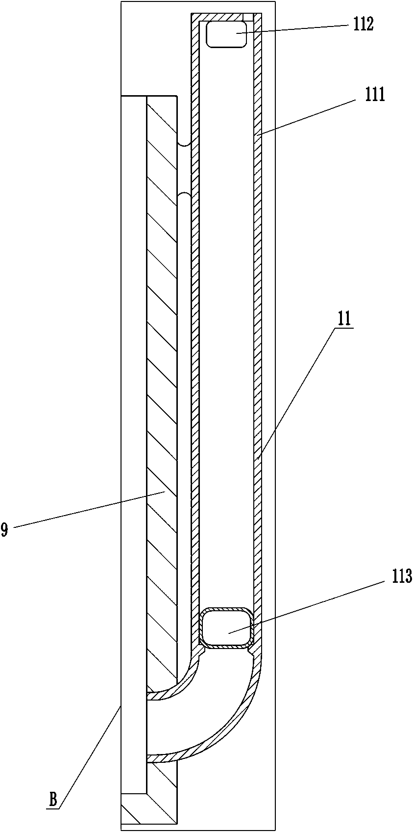
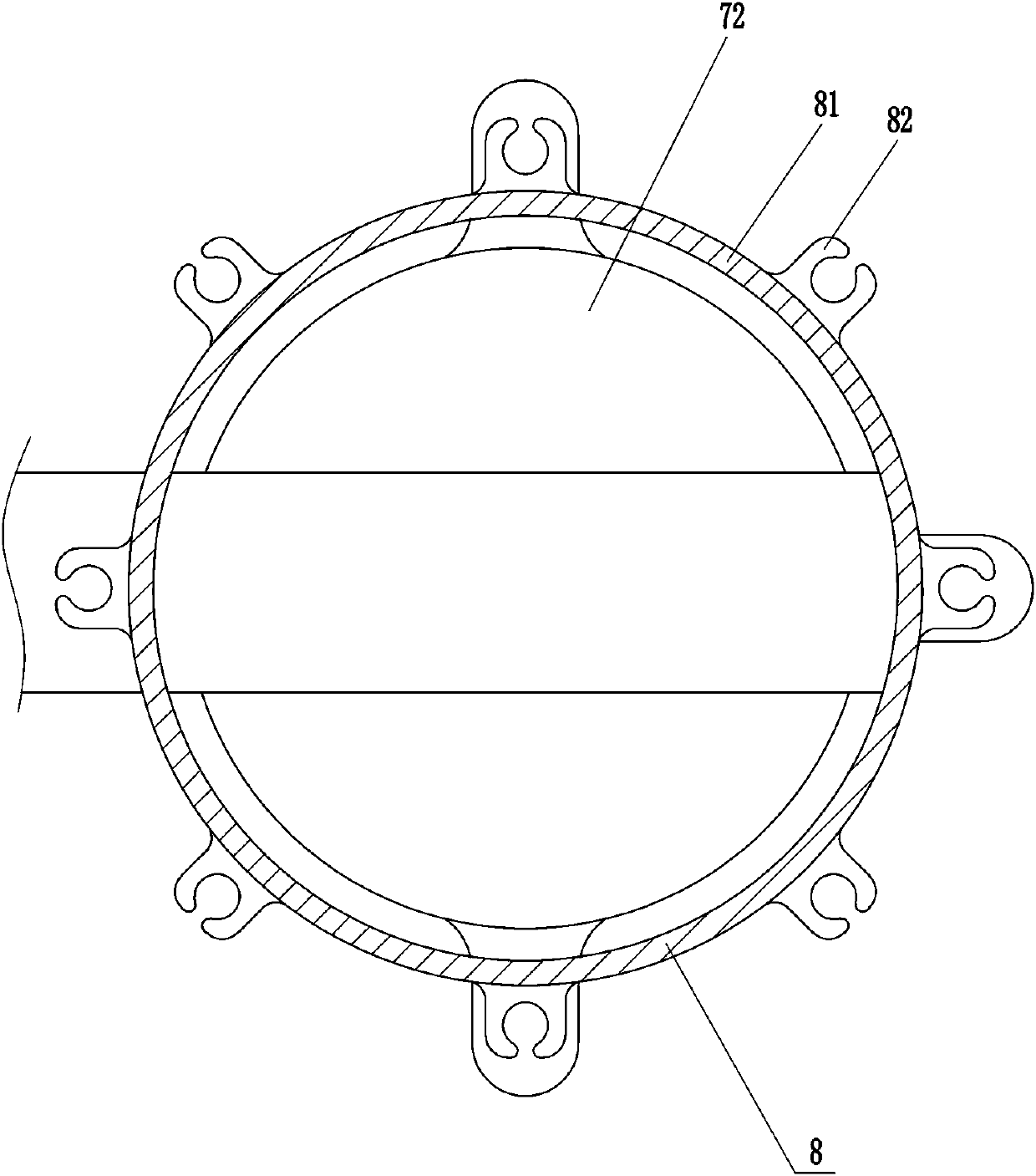
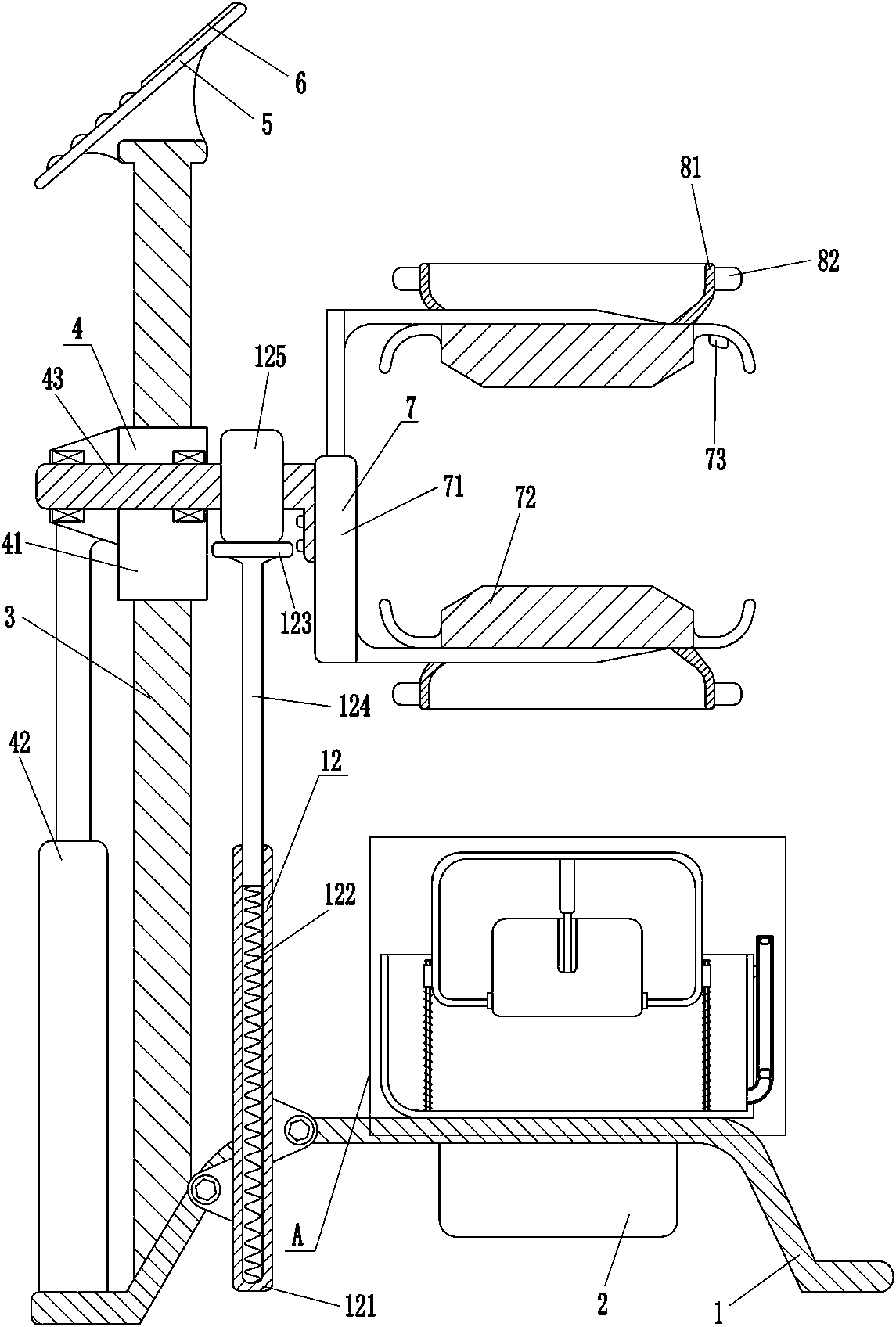
[0025] A new energy automobile motor stator enameled wire paint remover, such as figure 1 As shown, it includes a base 1, a pillar 3, a lifting mechanism 4, a clamping mechanism 7, a fixing mechanism 8, and a frame body 9. The left side of the top of the base 1 is fixed with a pillar 3, and the base 1 is connected to the pillar 3 by bolts. , the pillar 3 is provided with a lifting mechanism 4, the lifting mechanism 4 is used to drive the motor stator to move up and down, the lifting mechanism 4 is provided with a clamping mechanism 7, the clamping mechanism 7 is used to clamp the motor stator, and the clamping mechanism 7 is provided with There is a fixing mechanism 8, which is used to fix the terminal of the enameled wire, and a frame body 9 is arranged on the right side of the top of the base 1.

[0026] Such as figure 1 , Figure 5 with Image 6 Shown, also include control module, LCD display screen 6, setting key, plus one key, minus one key and confirmation key, LCD di...

Embodiment 2

[0035] On the basis of Example 1, such as image 3 As shown, a liquid level adjustment mechanism 10 is also included, and the liquid level adjustment mechanism 10 includes a slide bar 101, a first spring 102, a sliding sleeve 103, a box body 104, a filling block 105 and a third electric push rod 106, and the frame body 9 Slide bars 101 that play a guiding role are installed on the left and right sides of the inner bottom, and each slide bar 101 is slidably provided with a sliding sleeve 103, and a first spring 102 is connected between the sliding sleeve 103 and the inner bottom of the frame body 9. A spring 102 is wound on the sliding rod 101, and the box body 104 is connected between the sliding sleeves 103 on the left and right sides. The third electric push rod 106 is installed on the top of the box body 104, and the third electric push rod 106 is connected by bolts. Connected with the box body 104 , the bottom end of the third electric push rod 106 is connected with a fill...


PUM


Abstract

The invention relates to an enameled wire paint remover, in particular to a new energy automobile motor stator enameled wire paint remover. The technical problem is to provide a new energy automobilemotor stator enameled wire paint remover which can prevent a paint removing agent from staining hands of a worker and has high working efficiency. The new energy automobile motor stator enameled wirepaint remover comprises a base, a supporting column, a lifting mechanism and the like. The supporting column is fixedly connected to the left side of the top of the base. The lifting mechanism is arranged on the supporting column and used for driving a motor stator to move up and down. The motor rotor can be driven by the lifting mechanism to move downwards to soak the wiring end of an enameled wire in a paint removing agent and to remove the paint on the wiring end of the enameled wire, so that a worker is far away from the paint removing agent, and the paint removing agent can be prevented from staining the hands of the worker. Moreover, paint removal can be performed on the wiring ends of multiple enameled wires at a time, and the working efficiency is high.

Description

technical field [0001] The invention relates to an enameled wire paint remover, in particular to a new energy automobile motor stator enameled wire paint remover. Background technique [0002] The stator of the motor is the static part of the motor. The stator is composed of three parts: the stator core, the electronic winding and the machine base. Its main function is to generate a rotating magnetic field. In order to facilitate the connection of the line, it is necessary to remove the paint from the enameled wire terminal of the motor stator . [0003] Now generally the staff manually soaks the terminal of the enameled wire in the paint remover, and removes the paint from the terminal of the enameled wire. In this way, the paint remover may get on the hands of the staff and cause damage to the skin of the staff. And there are many enameled wires on the motor stator, but the staff can only remove the paint on a small amount of enameled wire terminals at one time, resulting...

Claims


Application Information

Patent Timeline
IPC IPC(8): H01R43/28
CPCH01R43/28H01R2201/10H01R2201/26
Inventor 不公告发明人
Owner 安徽国力电机有限公司
Why Eureka
Try Eureka