
Conveyor device and method for conveying shipments

A technology of conveying equipment and conveying parts, which is applied in the direction of conveyor objects, conveyors, transportation and packaging, etc., and can solve the problems of low acceleration, time-consuming, and flow reduction of light goods

Active Publication Date: 2022-05-13
KOERBER SUPPLY CHAIN LOGISTICS GMBH
View PDF7 Cites 0 Cited by
  • Summary
  • Abstract
  • Description
  • Claims
  • Application Information

AI Technical Summary

Problems solved by technology

The process takes time and brings a phase where the flow is significantly reduced
Adding to the difficulty is the low usable acceleration for light loads when it is desired to avoid uncontrolled skidding

Method used


Image

  • Conveyor device and method for conveying shipments
  • Conveyor device and method for conveying shipments
  • Conveyor device and method for conveying shipments

Examples


Embodiment Construction

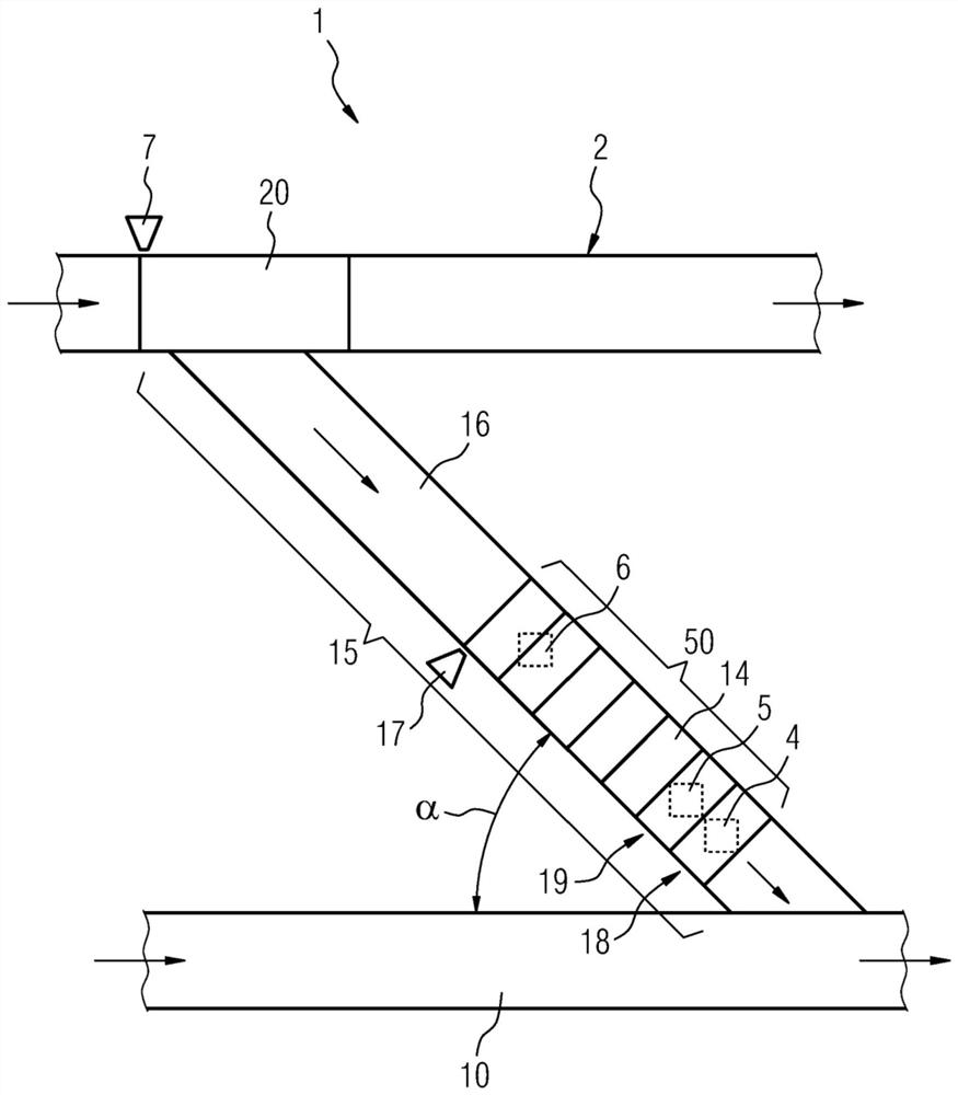
[0018] exist figure 1 A conveying device 1 according to the invention is shown in . The conveying device 1 here includes a conveying unit 2 which is designed for conveying item goods. The items 4 , 5 , 6 are transported, for example, by the transport unit 2 at a specific first transport speed. The conveying unit 2 is, for example, a conveying line, in which, for example, a plurality of different types of goods 4 , 5 , 6 are conveyed. The item goods 4 , 5 , 6 are conveyed on the conveying unit 2 in the direction of the arrows, for example. Furthermore, the transfer device 1 comprises a sorting unit 10 .

[0019] The respective items 4 , 5 , 6 are to be received and sorted from the conveyor unit 2 into the sorting unit 10 . The sorting unit 10 has, for example, a second conveying speed, wherein the conveying likewise takes place in the direction of the arrow purely by way of example. For this purpose, the sorting unit 10 provides a plurality of positions. For example, such...


PUM


Abstract

The invention proposes a conveying device (1), which comprises: a conveying unit (2); a sorting unit (10), which is configured to receive and sort items from the conveying unit (2); a conveying unit (15), It has an inlet unit (50), the transfer unit forming the transport connection between the conveyor unit (2) and the sorting unit (10), and an outlet unit (20), which is positioned on a section of the conveyor unit (2) And be configured for, only when said piece goods (4,5,6) have the predetermined minimum distance from the previous drawn piece goods (4,5,6) when described piece goods (4,5,6) Lead out to the transfer unit (15). Furthermore, a method for conveying a shipment is proposed.

Description

technical field [0001] The invention relates to a conveying device and a method for conveying goods. Background technique [0002] Conveying devices are known for conveying item goods such as, for example, parcels or tool pieces to sorting units. In this case, the problem usually arises that at medium flow rates (for example 3 kpph), states already occur during today's injection into the sorting unit, which drive medium-term flow rates which are significantly lower than the nominal flow rate of the injection. When stops occur regularly due to the lack of free space on the sorting unit, not only the injection, but also the entire conveying technology carrying out the feeding must be stopped. If the throughput is increased, the sequence of shipments per road segment must become longer. If a standstill occurs here, an unfavorable density must result, which must be eliminated during a restart (jamming in street traffic). The process takes time and brings about a phase in whic...

Claims


Application Information

Patent Timeline
Patent Type & Authority Patents(China)
IPC IPC(8): B07C1/02B65G43/08
CPCB07C1/02B65G43/08B65G47/5104B65G47/57B65G47/682B65G47/69B65G2203/0208B65G2203/0233B65G2203/042B65G47/46B65G47/42
Inventor 卡斯滕·阿施普维斯尼古劳斯·哈泽尔贝格尔塞巴斯蒂安·黑恩蒂姆·席斯
Owner KOERBER SUPPLY CHAIN LOGISTICS GMBH
Learn More