Supercharge Your Innovation With Domain-Expert AI Agents!

Photovoltaic device

A technology for equipment and adjustment equipment, applied in photovoltaic power generation, photovoltaic modules, photovoltaic system monitoring, etc., can solve problems and other problems

Active Publication Date: 2019-12-13
西门子能源全球两合公司
View PDF7 Cites 0 Cited by
  • Summary
  • Abstract
  • Description
  • Claims
  • Application Information

AI Technical Summary

Problems solved by technology

In this context, however, differently formed superimposed structures prove to be technically problematic

Method used


Image

  • Photovoltaic device
  • Photovoltaic device
  • Photovoltaic device

Examples


Embodiment Construction

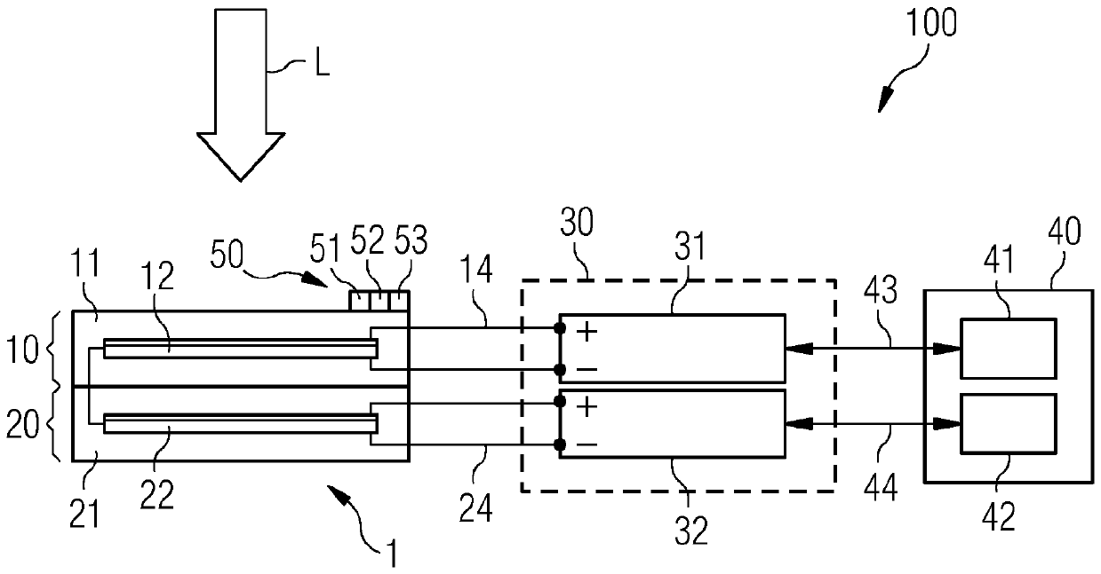
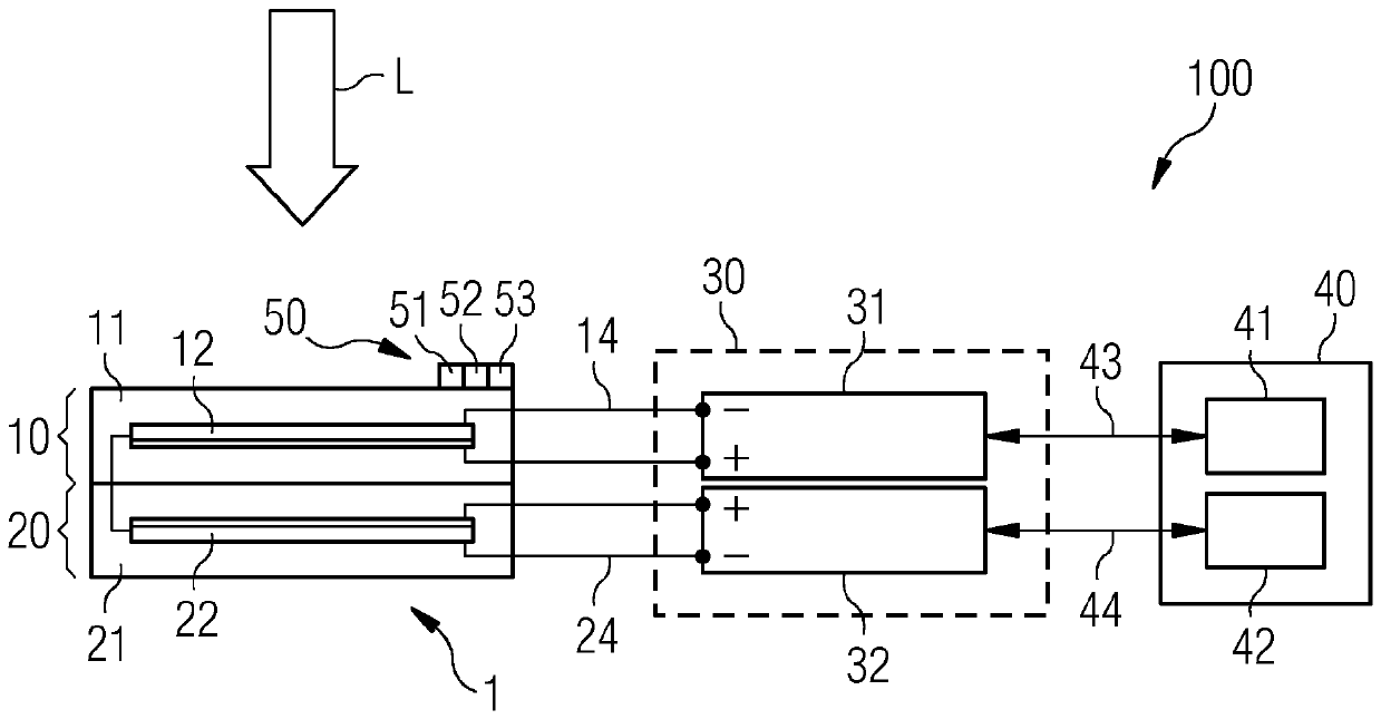
[0049] image 3 Shown is a PV installation 100 having a multi-PV cell stack 1 with a first PV cell 11 of a first cell type (that is to say, with one or more first photosensitive regions 12 of the first material) and second PV cells 21 of the second cell type (that is to say, with One or more second (not shown) photosensitive regions 22). A multi-PV cell stack 1 with two PV cells 11 , 21 is thus a series PV cell stack. For the sake of simplicity, the expression that the respective PV cells generate voltages (or similar) is generally used below, however this means that these voltages are generated by the respective photosensitive regions of the cells.

[0050] The battery cell group 1 is arranged during operation such that the first PV cell 11 faces a light source, such as the sun. The light L emitted by the light source and incident on the cell group 1 thus first encounters the first PV cell 11 , which in a known manner leads to the first PV cell 11 or its photosensitive reg...


PUM


Abstract

The invention relates to a tandem PV cell group (1) having two PV cells (11, 21) of different cell types. A separate power electronic unit (31, 32) is assigned to each of the PV cells in such a mannerthat a voltage generated in the particular PV cell or the corresponding power yield can be supplied to the assigned power electronic unit. The power electronic units can be operated independently ofone another with the aid of a control device (40) in such a manner that each PV subsystem having one of the PV cells in each case and the power electronic unit assigned to the particular PV cell operates at the optimum operating point thereof. For this purpose, the control device can operate in such a manner that, during operation of the power electronic unit of each PV subsystem, a product of thepower yield and the cell voltage of the PV cell assigned to the particular power electronic unit is at a maximum.

Description

technical field [0001] The invention relates to photovoltaic devices with two or more individual solar cells. Background technique [0002] Solar power generation using photovoltaic (PV) installations is contributing to electricity production to a rapidly increasing extent both for environmental reasons and also for increasing economic reasons (for example, in Central Europe). However, this renewable energy source must also be competitive and especially compared with conventional energy sources, for this reason even in regions with moderate solar radiation (such as Germany) it is sought to drive low-cost PV power generation than conventional (especially fossil energy production) costs. [0003] The cost of a PV installation is largely determined by system costs, such as for the overall panel, wiring, power electronics, and other structural costs. Although so-called perovskite materials such as CH3NH3PbI3 (or more generally, (CH3NH3)MX3-xYx (where M=Pb or Sn, and X, Y=I, Br...

Claims


Application Information

Patent Timeline
Patent Type & Authority Applications(China)
IPC IPC(8): H01L31/02H01L51/42H02S50/00H01L31/043
CPCH01L31/02021H02S50/10H01L31/043H01L25/043G05F1/67Y02E10/549Y02E10/56H10K30/57H10K85/50H02S40/30Y02E10/50H01L25/167H02S50/00
Inventor M.弗莱舍尔A.施内特勒
Owner 西门子能源全球两合公司
Features
  • R&D
  • Intellectual Property
  • Life Sciences
  • Materials
  • Tech Scout
  • Unparalleled Data Quality
  • Higher Quality Content
  • 60% Fewer Hallucinations
Learn More