Equipment for detecting terminal electrical performance

A technology of electrical performance testing and terminals, applied in the field of transportation testing, can solve the problems of low testing efficiency, increased cost, and more construction space

Pending Publication Date: 2019-12-17
昆山美佳合自动化设备有限公司
View PDF0 Cites 2 Cited by
  • Summary
  • Abstract
  • Description
  • Claims
  • Application Information

AI Technical Summary

Problems solved by technology

[0002] During the production process of the terminal, it is necessary to test its electrical properties. The traditional testing equipment contains multiple testing stations arranged in a straight line, which occupies a large area and has low testing efficiency. Secondly, after the testing is completed, the waste needs to be separated. The method of division is to increase the branch of the pipeline, resulting in too many branches of the transmission pipeline, occupying too much construction space and increasing the cost

Method used


Image

  • Equipment for detecting terminal electrical performance
  • Equipment for detecting terminal electrical performance
  • Equipment for detecting terminal electrical performance

Examples


Embodiment

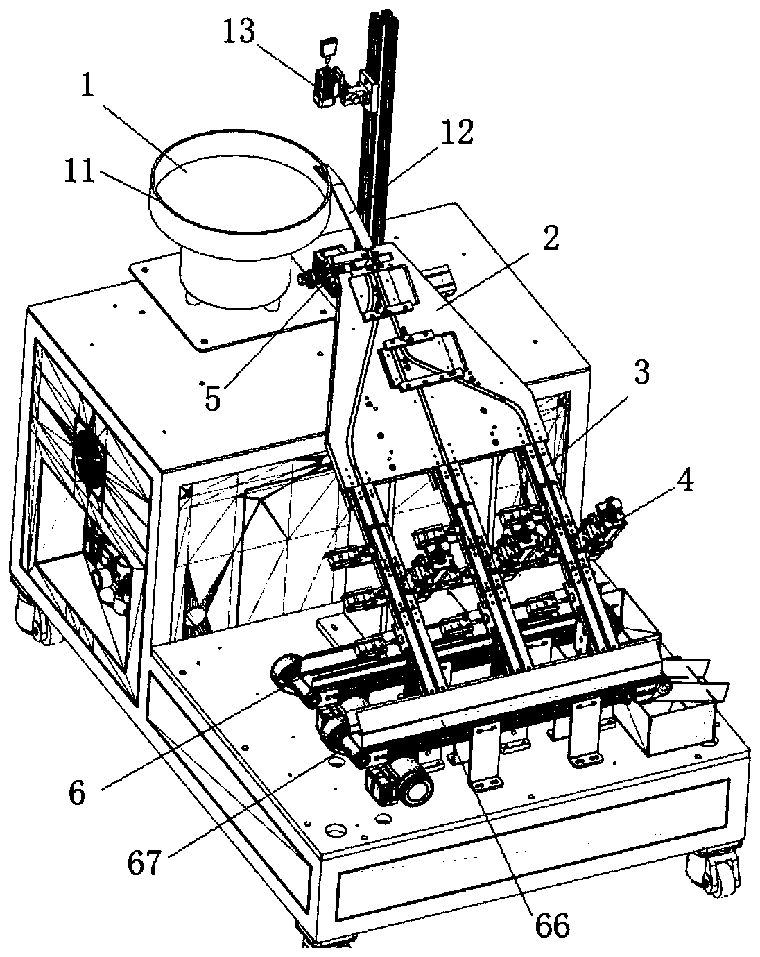
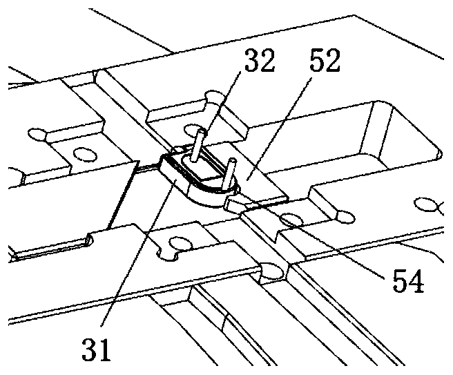
[0029] refer to Figure 1-6 As shown, this embodiment is a terminal electrical performance testing equipment, including a feeding device 1 for transferring materials, a dislocation device 2 arranged at the end of the feeding device 1 for distributing materials to each downstream conveying channel, and a dislocation device 2 arranged at the docking downstream The side of the detection slide rail 3 at the end of the conveying path and the detection device 4 for pressing down on the material 31 for electrification detection, and the material leakage device 6 provided on the detection slide rail 3 for pushing out waste from the side.

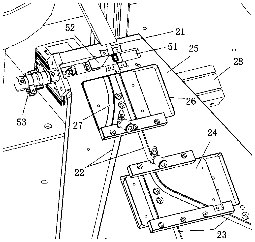
[0030] The dislocation device 2 comprises some multi-stage material passing plates 24, a main conveying path 21 and some descending conveying paths, and the descending conveying path comprises a secondary conveying path 22 and a branch conveying path 23; Distributed to several downstream conveying lanes 22, the single secondary conveying lane 22 or ...


PUM


Abstract

The invention discloses equipment for detecting terminal electrical performance, and belongs to the technical field of transportation detection. The equipment specifically comprises a feeding device which is used for transferring materials, a dislocating device which is arranged at the tail end of the feeding device and is used for distributing materials to each downlink conveying channel, a detecting device which is arranged at the side edge of a detecting sliding rail for abutting joint the tail ends of the downlink conveying channels and is used for pressing down to the materials for detecting electrically, and a material leakage device which is arranged on the detecting sliding rail and is used for pushing out waste materials on the side edge. The equipment for detecting the terminal electrical performance is used for realizing reasonable optimization of pipeline distribution so as to achieve efficient transportation of detecting products and reasonable waste discharge.

Description

technical field [0001] The invention belongs to the technical field of transportation detection, and in particular relates to a terminal electrical performance detection device. Background technique [0002] During the production process of the terminal, it is necessary to test its electrical performance. The traditional testing equipment includes multiple testing stations arranged in a straight line, which occupies a large area and has low testing efficiency. Secondly, after the testing is completed, the waste needs to be separated. The division method adopts the branch of the pipeline, resulting in too many branches of the transmission pipeline, occupying too much construction space and increasing the cost. Contents of the invention [0003] The purpose of the present invention is to solve the above technical problems, and provide terminal electrical performance testing equipment, so as to realize reasonable optimization of assembly line distribution, efficient transport...

Claims


Application Information

Patent Timeline
Patent Type & Authority Applications(China)
IPC IPC(8): B07C5/344
CPCB07C5/344
Inventor 赵福仲
Owner 昆山美佳合自动化设备有限公司
Why Eureka
Try Eureka