Pre-oxidation furnace with end-to-end blowing structure

A pre-oxidation furnace, end-to-end technology, applied in the field of oxidation furnace, can solve the problems of large sag, unfavorable installation of air outlet devices, etc., and achieve the effect of solving inconvenient installation

Pending Publication Date: 2019-12-17
ZHEJIANG JINGGONG SCI & TECH
View PDF10 Cites 6 Cited by
  • Summary
  • Abstract
  • Description
  • Claims
  • Application Information

AI Technical Summary

Problems solved by technology

[0011] Most of the existing air outlet devices are arranged in the middle of the wire passage, so as to blow air to both ends of the wire passage; when the fibers are distributed in a serpentine shape, the sag of the wire is relatively large, which is not conducive to the installation of the air outlet device

Method used


Image

  • Pre-oxidation furnace with end-to-end blowing structure
  • Pre-oxidation furnace with end-to-end blowing structure
  • Pre-oxidation furnace with end-to-end blowing structure

Examples


Embodiment 1

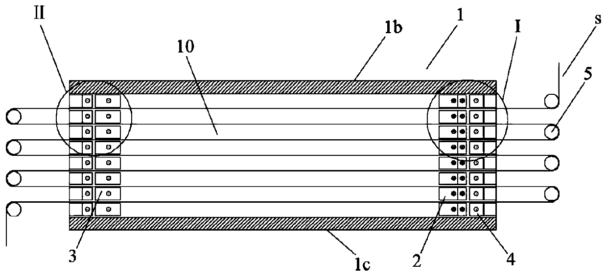
[0049] Such as Figure 1-7 As shown, the pre-oxidation furnace of the end-to-end blowing structure of the present embodiment includes a furnace body 1 and an air outlet device 2 installed in the furnace body, a first air return device 3 and a second return air device 4, and also includes a corresponding The guide roller 5 that the left and right ends of furnace body 1 is installed.

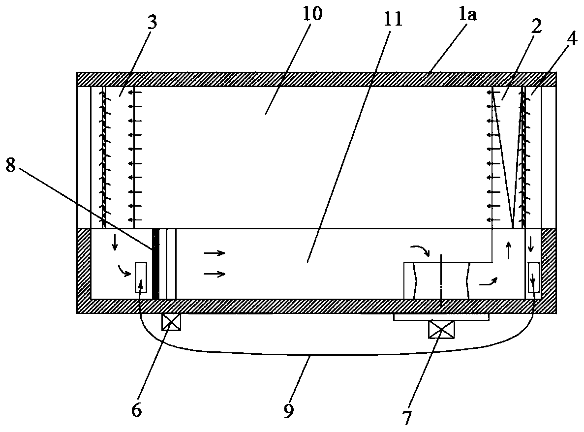
[0050] Such as figure 1 and 2 As shown, the furnace body 1 is surrounded by two vertical side walls 1a opposite in the length direction, two vertical end walls opposite in the width direction, a top wall 1b, and a bottom wall 1c. Hollow rectangular parallelepiped structure; the end walls at the left and right ends of the furnace body have seven groups of through-holes arranged at vertical intervals (the number of through-hole groups is not limited to the seven groups in this embodiment, and can be freely designed according to actual needs).

[0051] Such as figure 2 As shown, the furnace body...

Embodiment 2

[0059] The difference between the preoxidation furnace of the end-to-end blowing structure of the present embodiment and embodiment one is:

[0060] Such as Figure 8 As shown, a first mesh plate A corresponding to the first air return port and a second mesh plate B corresponding to the second air return port are installed in the furnace body to ensure the uniformity and stability of the return air.

[0061] The long-term movement of the pre-oxidation furnace will easily block the first mesh plate A and the second mesh plate B; therefore, it is necessary to clean the first mesh plate and the second mesh plate online, specifically, as Figure 9 and 10 As shown, the furnace body of the present embodiment has a draw-in port C corresponding to the first mesh plate and the second mesh plate one by one, and the draw-in port C is equipped with a thermal insulation sealing plug D. By pulling out the insulation sealing plug, the first mesh plate or the second mesh plate can be pulled...


PUM


Abstract

The invention relates to a pre-oxidation furnace with an end-to-end blowing structure. The pre-oxidation furnace comprises a furnace body, and the furnace body is provided with a wire feeding channeland an air return channel which are distributed in the length direction of the furnace body; a first air return device and an air outlet device are arranged at two ends of the wire feeding channel respectively, and a second air return device is arranged at the side, away from the first air return device, of the air outlet device; the first air return device comprises a plurality of first air return boxes which are arranged at intervals vertically; the air outlet device comprises a plurality of distributors which are arranged at intervals vertically; the second air return device comprises a plurality of second air return boxes which are arranged at intervals vertically; a heater and an air blower are installed in the air return channel, the air blower blows hot air, heated by the heater, inthe air return channel into the wire feeding channel through the distributors, and the hot air in the wire feeding channel enters the first air return boxes in a first air return direction and the second air return boxes in a second air return direction and converges to the upstream end of the air return channel. The furnace solves the problem of inconvenient installation, caused by large fiber sag, of the distributors.

Description

technical field [0001] The invention belongs to the technical field of oxidation furnaces, in particular to a pre-oxidation furnace with an end-to-end blowing structure. Background technique [0002] In the process of carbon fiber production, the pre-oxidation of the precursor plays a role of connecting the past and the future, and the pre-oxidation process of the precursor directly affects the yield and performance of carbon fiber. The purpose of the pre-oxidation process is to convert the thermoplastic PAN linear macromolecular chain into a non-plastic heat-resistant trapezoidal structure, making it infusible and non-combustible at high carbonization temperatures, maintaining the fiber shape, and thermodynamically in a stable state, and finally transforming into a turbostratic graphite structure. carbon fiber. According to the requirements of the pre-oxidation process, the pre-oxidation furnace came into being. [0003] Existing pre-oxidation furnaces generally include: ...

Claims


Application Information

Patent Timeline
Patent Type & Authority Applications(China)
IPC IPC(8): D01F9/12D01F9/32
CPCD01F9/12D01F9/32
Inventor 金振峰傅建根张瑜王永法韩剑飞韩宝灯傅春峰
Owner ZHEJIANG JINGGONG SCI & TECH
Why Eureka
Try Eureka