Defect detection method for product of mirror surface bowl-shaped structure

A defect detection and product technology, applied in the field of visual inspection, can solve the problems of reduced imaging contrast, poor imaging of large spots, etc., and achieve the effect of improving quality and production capacity

Active Publication Date: 2019-12-17
BEIJING FOCUSIGHT TECH
View PDF7 Cites 0 Cited by
  • Summary
  • Abstract
  • Description
  • Claims
  • Application Information

AI Technical Summary

Problems solved by technology

For the surface inspection of mirror products, the imaging generally needs to form a spot effect to have a good defect presentation, but for products with a mirror surface and a bowl shape at the same time, the imaging problem cannot be solved well
According to the characteristics that the dome light source can reduce the impact of surface unevenness, the imaging contrast is reduced when the dome light source is used for imaging.
Using a customized large-area vertical ring light and a large-size parallel coaxial test, the large-area vertical ring light can obtain a re

Method used


Image

  • Defect detection method for product of mirror surface bowl-shaped structure
  • Defect detection method for product of mirror surface bowl-shaped structure
  • Defect detection method for product of mirror surface bowl-shaped structure

Examples


Example Embodiment

[0025] Example 1

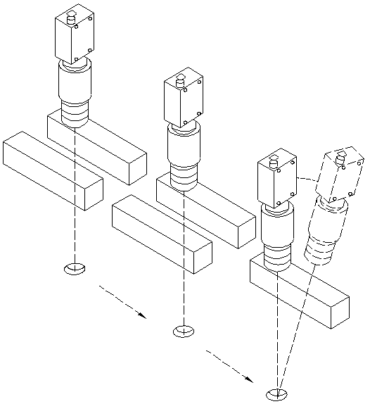
[0026] A defect detection method for mirror bowl-shaped structure products, such as figure 1 The imaging device shown includes a first camera, a second camera and a third camera arranged side by side, the first camera corresponds to the first group of bar light sources, the second camera corresponds to the second group of bar light sources, and the third camera corresponds to the third A group of bar-shaped light sources, the first group of bar-shaped light sources and the second group of bar-shaped light sources have two bar-shaped light sources, and the third group of bar-shaped light sources is one bar-shaped light source.

[0027] During the specific operation, first place the mirror bowl-shaped structure product to be inspected on the carrying table (the carrying table is fixed on the conveyor belt and moves with the conveyor belt), adjust the positions of all cameras, and ensure that all cameras are in an upright state; When the inspection product mov...


PUM

PropertyMeasurementUnit
Heightaaaaaaaaaa

Abstract

The invention relates to a defect detection method for a product of a mirror surface bowl-shaped structure. A part of the surface of the product to be detected is imaged in sequence by adopting a plurality of cameras and corresponding strip-shaped light sources, all defects on the surface of the product are well presented, the problem that the surface defects of the high-reflection mirror bowl-shaped product cannot be imaged is solved, automatic detection of the product is realized, and improvements of the quality and productivity of the production line are facilitated.

Description

technical field [0001] The invention relates to the technical field of visual inspection, in particular to a defect detection method for mirror-surface bowl-shaped structure products. Background technique [0002] With the continuous development of society, the degree of industrial automation is getting higher and higher, not only production is replaced by machines, but manual inspection will also be replaced by machines, so machine vision is widely used. In all surface defect inspection, the goal of imaging exploration must be to find an imaging method that can obtain better defect contrast and uniform image. For the surface inspection of mirror products, imaging generally needs to form a spot effect in order to have a good defect presentation, but for products with a mirror surface and a bowl shape, the imaging problem cannot be well solved. According to the characteristics that the dome light source can reduce the influence of surface unevenness, the imaging contrast is ...

Claims


Application Information

Patent Timeline
IPC IPC(8): G01N21/88
CPCG01N21/8806G01N21/8851G01N2021/8887
Inventor 王郑王岩松马凯周子健
Owner BEIJING FOCUSIGHT TECH
Why Eureka
Try Eureka