pixel circuit

A technology of pixel circuit and capacitor, which is applied in the field of pixel circuit to achieve the effect of reducing power consumption

Active Publication Date: 2021-09-03
AU OPTRONICS CORP
View PDF4 Cites 0 Cited by
  • Summary
  • Abstract
  • Description
  • Claims
  • Application Information

AI Technical Summary

Problems solved by technology

The voltage selector selects the first reference voltage or the data voltage according to the laser control signal and the first scan signal to generate a selection voltage

Method used


Image

  • pixel circuit
  • pixel circuit
  • pixel circuit

Examples


Embodiment Construction

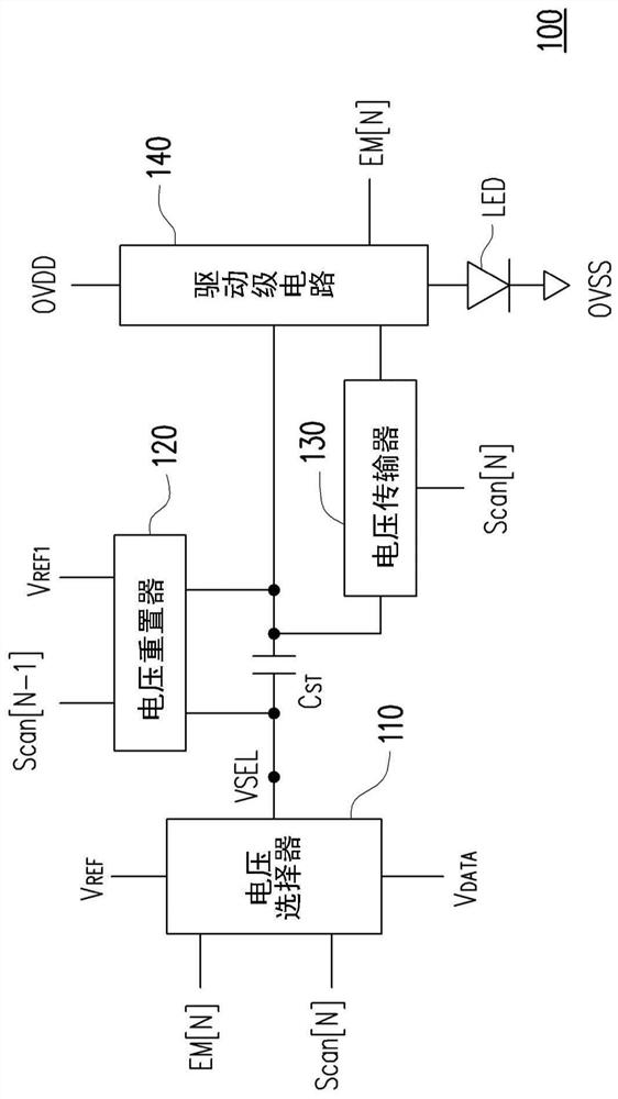
[0033] Please refer to figure 1 , figure 1 A schematic diagram showing a pixel circuit according to an embodiment of the present invention. In this embodiment, the pixel circuit 100 is used to drive the light emitting diode LED. The pixel circuit 100 includes a voltage selector 110, a capacitor C ST , a voltage reset device 120 , a driver stage circuit 140 and a voltage transmitter 130 . The voltage selector 110 selects the reference voltage V according to the laser control signal EM[N] and the scanning signal Scan[N] REF or data voltage V DATA to generate the selection voltage VSEL. The voltage selector 110 is coupled to the capacitor C ST The first end of the , and provide the selection voltage VSEL to the capacitor C ST the first end of . The voltage reset device 120 is coupled to the capacitor C ST the first end and the second end. The voltage reset unit 120 receives the scan signal Scan[N-1] to provide a reference voltage V REF1 . The voltage reset unit 120 pr...


PUM


Abstract

The application discloses a pixel circuit for driving a light emitting diode. The pixel circuit includes a voltage selector, a capacitor, a voltage reset device, a driving stage circuit and a voltage transmitter. The voltage selector selects the first reference voltage or the data voltage to generate the selection voltage according to the laser control signal and the first scan signal. The first terminal of the capacitor receives the selection voltage. The voltage reset device provides a second reference voltage to the first terminal and the second terminal of the capacitor according to the second scan signal. The driving stage circuit drives the LED according to the voltage on the second terminal of the capacitor and the laser control signal. The voltage transmitter provides a voltage transmission path between the second end of the capacitor and the driver circuit according to the first scanning signal.

Description

technical field [0001] The invention relates to a pixel circuit, and in particular to a pixel circuit of a light emitting diode. Background technique [0002] With the evolution of electronic technology, consumer electronic products have become an important tool for people's daily life. It is an important trend to provide high-efficiency display devices on consumer electronic products. [0003] In the current technical field, display devices constructed by using light emitting diodes are becoming more and more popular. In the pixel circuit used to drive light-emitting diodes, the driving transistor will have the problem of variation in electrical characteristics under long-term use or during the manufacturing process. Therefore, how the pixel circuit provides a highly consistent driving current is the key to the display quality of the image display device. Key factor. Moreover, how to reduce the power consumption of the display device and how to improve the contrast of th...

Claims


Application Information

Patent Timeline
Patent Type & Authority Patents(China)
IPC IPC(8): G09G3/32
CPCG09G3/32G09G2330/021
Inventor 赖柏君郑贸薰陈勇志
Owner AU OPTRONICS CORP
Why Eureka
Try Eureka