Cell assembling structure of combined battery

A combined battery and assembly structure technology, applied in the direction of secondary batteries, secondary battery manufacturing, circuits, etc., can solve problems affecting the consistency of combined batteries, changes in cell resistivity, deformation connections, etc., to improve connection stability, Effects of weight reduction and interference avoidance

Pending Publication Date: 2019-12-17
江苏富能宝储能科技有限公司
View PDF0 Cites 0 Cited by
  • Summary
  • Abstract
  • Description
  • Claims
  • Application Information

AI Technical Summary

Problems solved by technology

However, because the positive and negative tabs of the single battery core protrude upward from the top of the battery core, and the positive and negative tabs of the battery core do not protrude upward along the two sides of the battery core, that is, the distance between the bottom of the positive and negative tabs of the battery core There is a certain vacancy on the side of the battery, so when the positive and negative tabs are bent and connected, there must be some space between the bottom of the positive and negative tabs and the cell frame without any support, so that once our cell frame is in the handling process Vibration, deformation, etc. during use or shaking during use can easily cause deformation or loose connection of our positive and negative tabs, and these conditions will directly lead to changes in the resistivity of the battery cell, which in turn will affect the entire combined battery. Consistency

Method used


Image

  • Cell assembling structure of combined battery
  • Cell assembling structure of combined battery
  • Cell assembling structure of combined battery

Examples


Embodiment Construction

[0021] The following will clearly and completely describe the technical solutions in the embodiments of the present invention with reference to the accompanying drawings in the embodiments of the present invention. Obviously, the described embodiments are only some, not all, embodiments of the present invention. Based on the embodiments of the present invention, all other embodiments obtained by persons of ordinary skill in the art without making creative efforts belong to the protection scope of the present invention.

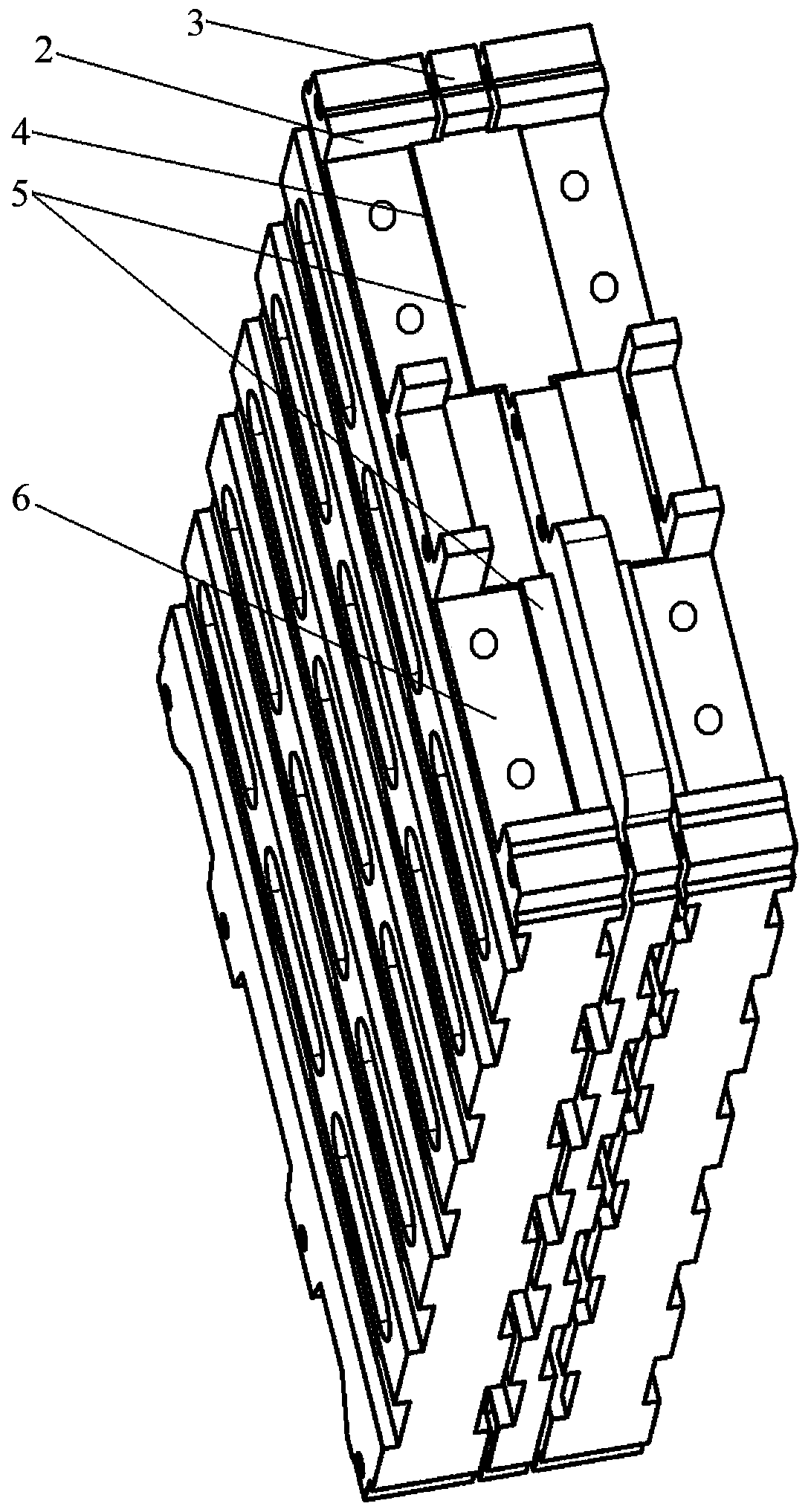
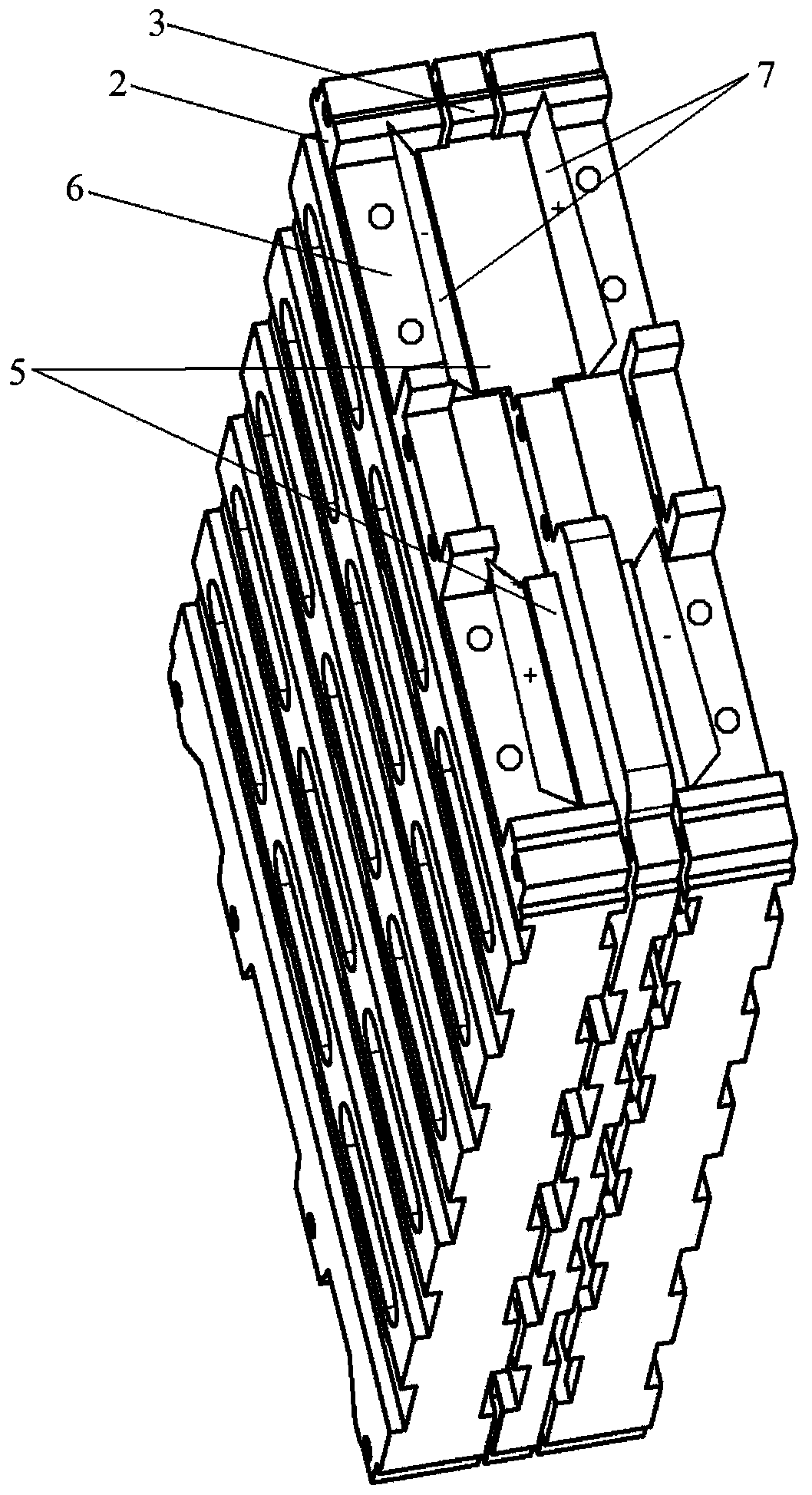
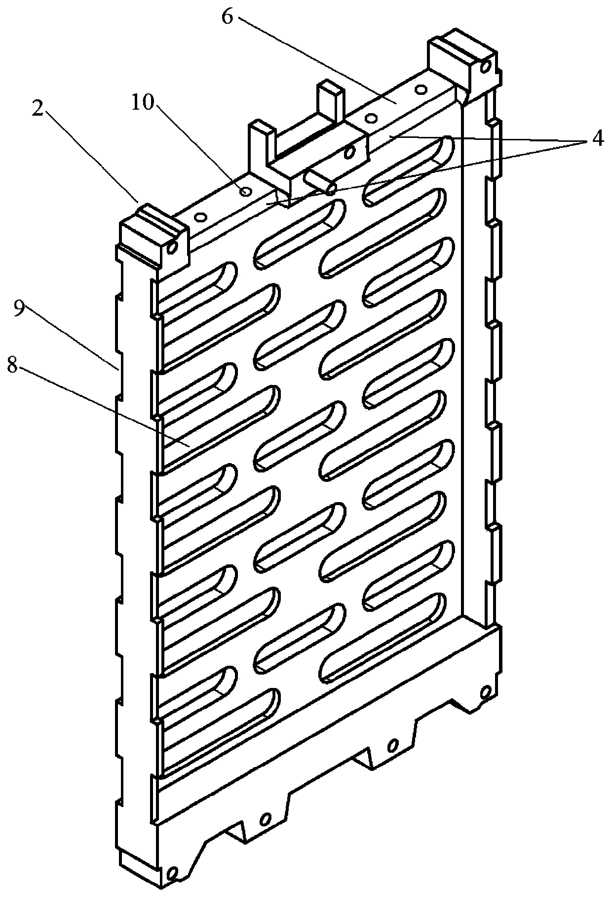
[0022] like Figures 1 to 5 As shown, a cell assembly structure of an assembled battery includes a plurality of single cells 1 and a cell frame 2, the single cells 1 are connected in series, and each single cell 1 is installed on the cell Inside the frame body 2 , each cell frame body 2 is assembled side by side with each other. One side of the cell frame 1 is an open structure, and the open side is used to put in the cell 1, and at the same time, there are t...


PUM


Abstract

The invention discloses a cell assembling structure of a combined battery. The cell assembling structure comprises a plurality of single cells and cell frames. The single cells are connected in serieswith each other, and each single cell is installed in the cell frame. All the cell frames are assembled in parallel with each other. One side surface of each cell frame has an open structure, and twolead-out grooves for leading out the positive and negative lugs of the single cell are arranged on the side of the top end close to the opening direction and a spacer is arranged between the adjacentcell frames. The top two sides of the spacer are provided with outwardly extending fixing bosses. After the spacer is assembled in parallel with the cell frame, the fixing bosses of the spacer are embedded in the lead-out grooves of the cell frame. The connection stability of the cell electrode lugs can be greatly improved, and the influence on the consistency of the whole combined battery causedby the change of the cell resistivity because of the deformation of the electrode lugs can be avoided. Meanwhile, the structure also has the advantages of good heat dissipation performance and high anti-interference capability.

Description

technical field [0001] The invention belongs to the technical field of battery energy storage, and in particular relates to a cell assembly structure of a combined battery. Background technique [0002] The voltage and power of the battery PARK cells are relatively small, which cannot meet the application requirements of energy storage systems and electric vehicles. It is necessary to connect multiple battery PARK cells in series to form a high-voltage battery string. Usually in the assembly process, the single cells are placed in the cell frame, and then the cell frames are assembled side by side. After the frame is assembled, the positive and negative tabs of the adjacent cells are connected by conductive The slices are connected to realize the series connection of each cell. However, because the positive and negative tabs of the single battery core protrude upward from the top of the battery core, and the positive and negative tabs of the battery core do not protrude upw...

Claims


Application Information

Patent Timeline
Patent Type & Authority Applications(China)
IPC IPC(8): H01M10/04H01M10/613H01M10/6561
CPCH01M10/04H01M10/0486H01M10/613H01M10/6561Y02E60/10Y02P70/50
Inventor 周锡卫杨丰艺李青松
Owner 江苏富能宝储能科技有限公司
Why Eureka
Try Eureka