Phase change temperature control device applied to battery pack

A phase-change temperature control and battery pack technology, which is applied to secondary batteries, circuits, electrical components, etc., can solve the problems of high cost, low heat dissipation energy at high temperature, and low sealing level, and achieve the effect of simple structure

Inactive Publication Date: 2019-12-17
GUANGZHOU HKUST FOK YING TUNG RES INST
View PDF3 Cites 5 Cited by
  • Summary
  • Abstract
  • Description
  • Claims
  • Application Information

AI Technical Summary

Problems solved by technology

[0003] At present, the commonly used thermal management methods of power battery packs are as follows: 1. Active air cooling method, which has the advantages of high heat dissipation capacity and moderate cost, but the disadvantages of low sealing level, uneven temperature field distribution, and low start-up efficiency at low temperature; 2. 1. The active liquid cooling method has the advantages of high heat dissipation capacity, high start-up efficiency at low temperature, and good sealing. The disadvantage is that the cost is high and the structure is complicated; 3. The passive air cooling method has the advantages of simple structure and low cost, and the disadvantage is the shape. Special design is required, low heat dissipation energy at high temperature, low start-up efficiency at low temperature, and uneven distribution of temperature field; 4. Passive liquid cooling method has the advantages of simple structure, low cost, good sealing, high start-up efficiency at low temperature, and the disadvantage of heat dissipation energy at high temperature Low; 5. Semiconductor refrigeration, which has the advantages of high cooling efficiency and simple structure, but the disadvantage is that it cannot cope with the impact of ambient temperature on the battery pack when the battery pack is not working
[0004] In the prior art, it is mainly aimed at the heat dissipation of the battery pack when it is working, but when the battery pack is not working, the battery pack will still be affected by the external ambient temperature. Too high or too low ambient temperature will affect the life of the battery pack.

Method used


Image

  • Phase change temperature control device applied to battery pack
  • Phase change temperature control device applied to battery pack

Examples


Embodiment Construction

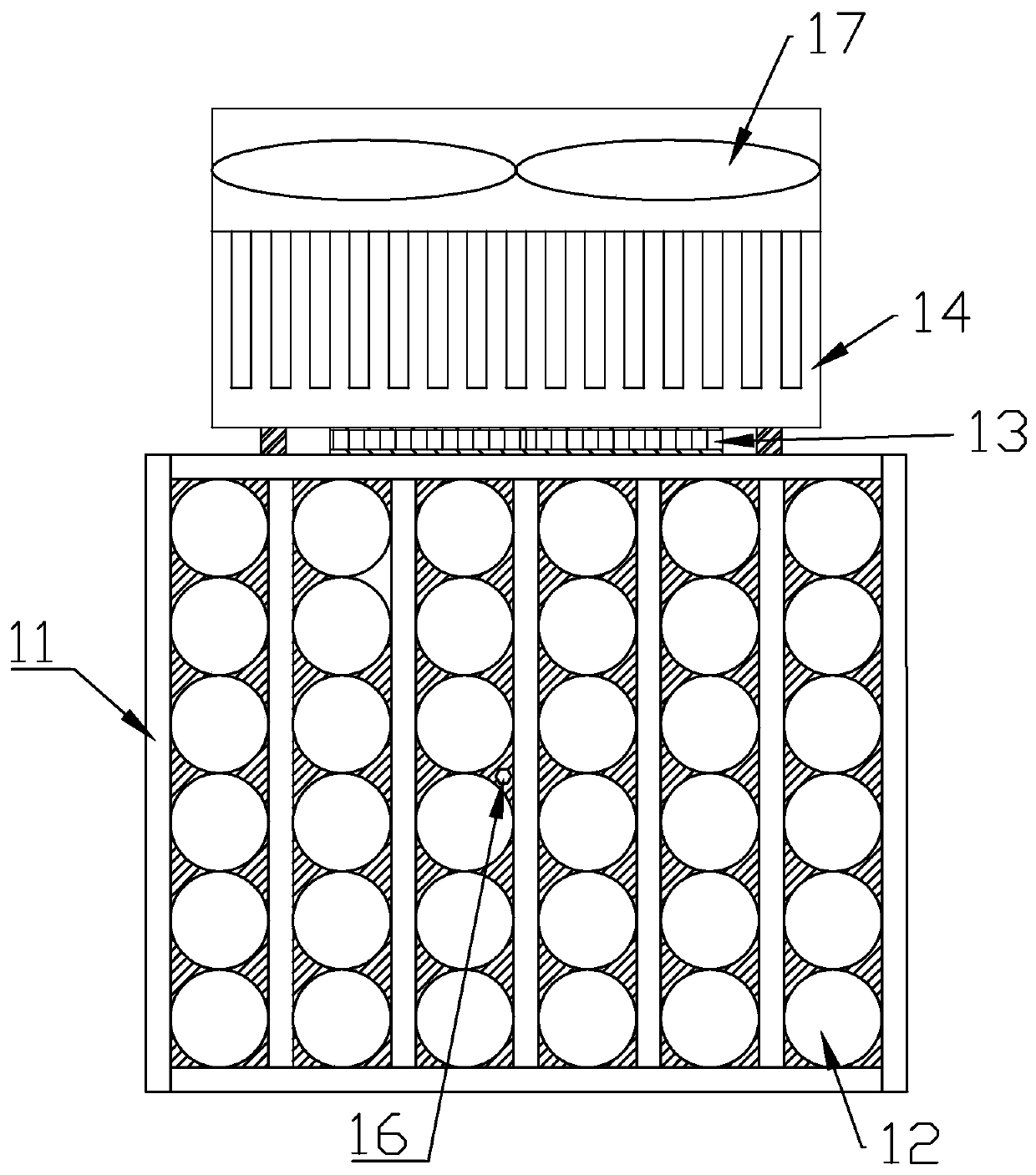
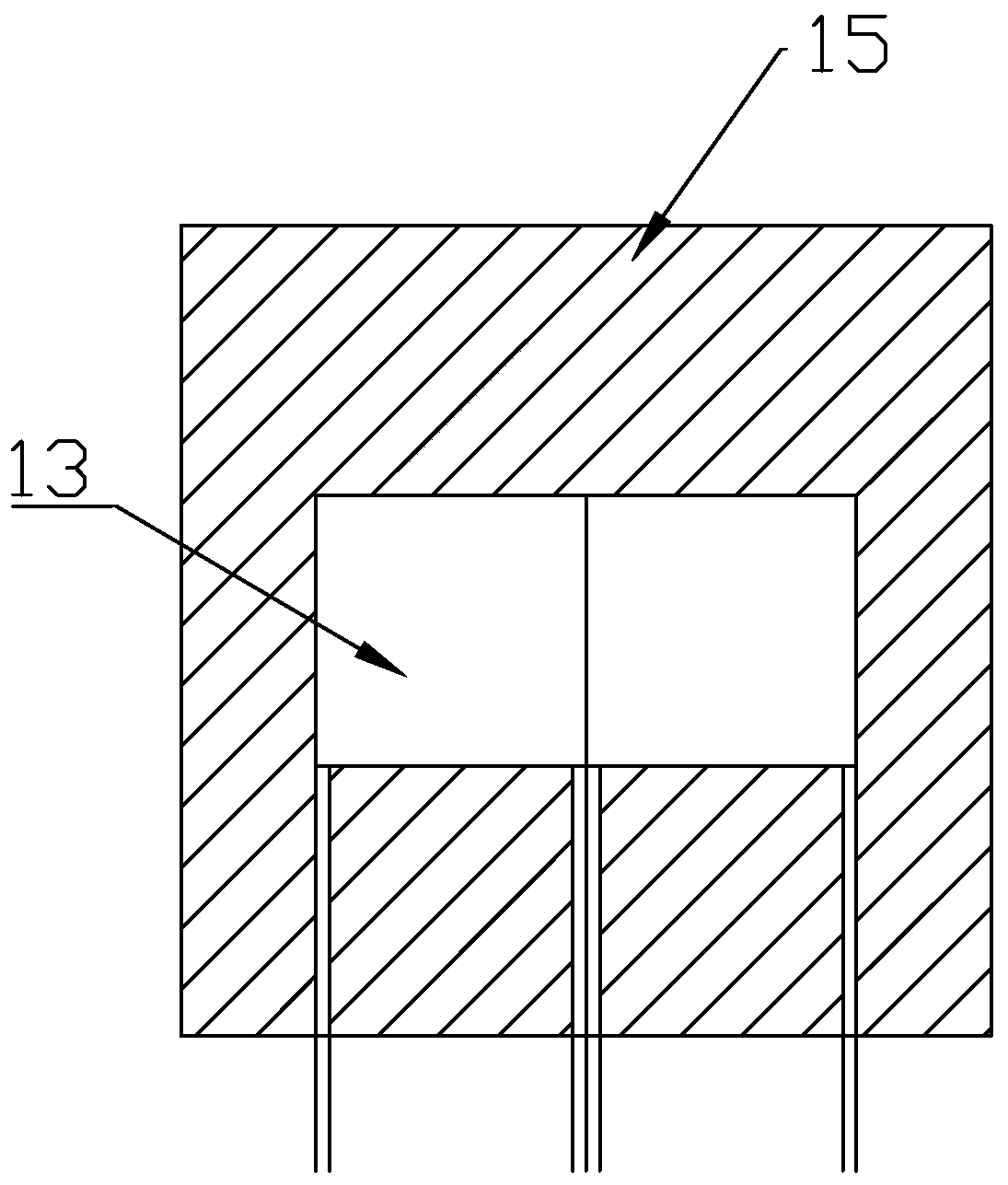
[0018] Combine below Figure 1 to Figure 2 The present invention is further described.

[0019] The invention relates to a phase change temperature control device applied to a battery pack, which includes a casing 11, the side wall of which is a thermally conductive aluminum plate. A temperature control module is arranged on the outer side of the housing 11, and the temperature control module includes a semiconductor cooling chip 13, and the semiconductor cooling chip 13 can be selected as one piece or multiple pieces arranged in an array. A heat insulation board 15 is arranged on the outside of the semiconductor cooling chip 13 , and the semiconductor cooling chip 13 is embedded in the heat insulating board 15 . A plurality of unit cavities 12 for placing batteries are arranged in the housing 11, each unit cavities 12 are arranged in an array, and the spaces between the unit cavities 12 are filled with composite fillers. After the battery is arranged in the unit cavity 12, ...


PUM

PropertyMeasurementUnit
phase transition temperatureaaaaaaaaaa
phase transition enthalpyaaaaaaaaaa
thicknessaaaaaaaaaa

Abstract

The invention discloses a phase change temperature control device applied to a battery pack. The phase change temperature control device comprises a housing. A plurality of unit cavities for placing batteries are arranged in the housing. The unit cavities are filled with composite fillers. A temperature control module is arranged on the outer side of the housing. The temperature control module comprises semiconductor refrigeration sheets. Through cooperation of the semiconductor refrigeration sheets and the composite fillers, temperature control is achieved; the temperature of the battery packcan be controlled through heat absorption or heat release of the composite fillers; and the temperature of the battery pack can be controlled by starting cooperative work of the semiconductor refrigeration sheets and the composite fillers, so that the temperature of the battery pack is flexibly controlled. The provided device is simple in structure and can be widely applied to the technical fieldof power battery pack thermal management.

Description

technical field [0001] The invention relates to the technical field of power battery pack heat management, in particular to a phase change temperature control device applied to a battery pack. Background technique [0002] As the main energy storage form of electric vehicles, power batteries directly restrict the power, economy and safety of electric vehicles. Compared with other types of batteries, lithium-ion batteries have strong advantages in terms of energy density, power density, and service life. Therefore, lithium-ion batteries have become the mainstream of vehicle power batteries. However, its performance, life and safety are closely related to the ambient temperature. Problems will arise when the operating temperature is too high or too low, or the temperature in the battery pack is inconsistent. Therefore, the adaptability of lithium-ion batteries to temperature has become one of the key factors restricting its application in electric vehicles, and it also makes ...

Claims


Application Information

Patent Timeline
Patent Type & Authority Applications(China)
IPC IPC(8): H01M10/613H01M10/615H01M10/617H01M10/625H01M10/658H01M10/6572H01M10/659H01M10/653H01M10/6554H01M10/637H01M10/6563
CPCH01M10/613H01M10/615H01M10/617H01M10/625H01M10/637H01M10/653H01M10/6554H01M10/6563H01M10/6572H01M10/658H01M10/659Y02E60/10
Inventor 杨晶磊安金亮郭晔
Owner GUANGZHOU HKUST FOK YING TUNG RES INST
Why Eureka
Try Eureka