Inferior heavy oil fluidization conversion technology

A low-quality heavy oil and process technology, which is applied in the petroleum industry, granular/powdered fuel gasification, and the manufacture of combustible gas, etc., can solve the problems of large equipment investment and complicated operation, and achieve low investment, increase yield, save equipment and The effect of heating furnace

Active Publication Date: 2013-07-31
SHANGHAI HOTO PETROCHEM ENG
View PDF4 Cites 4 Cited by
  • Summary
  • Abstract
  • Description
  • Claims
  • Application Information

AI Technical Summary

Problems solved by technology

The process adopts three reactors: pyrolysis reactor, pre-burned charcoal device and gasifier. The gasifier uses internal rotation separation, which requires large equipment investment and complicated operation.

Method used


Image

  • Inferior heavy oil fluidization conversion technology
  • Inferior heavy oil fluidization conversion technology
  • Inferior heavy oil fluidization conversion technology

Examples


Embodiment 1

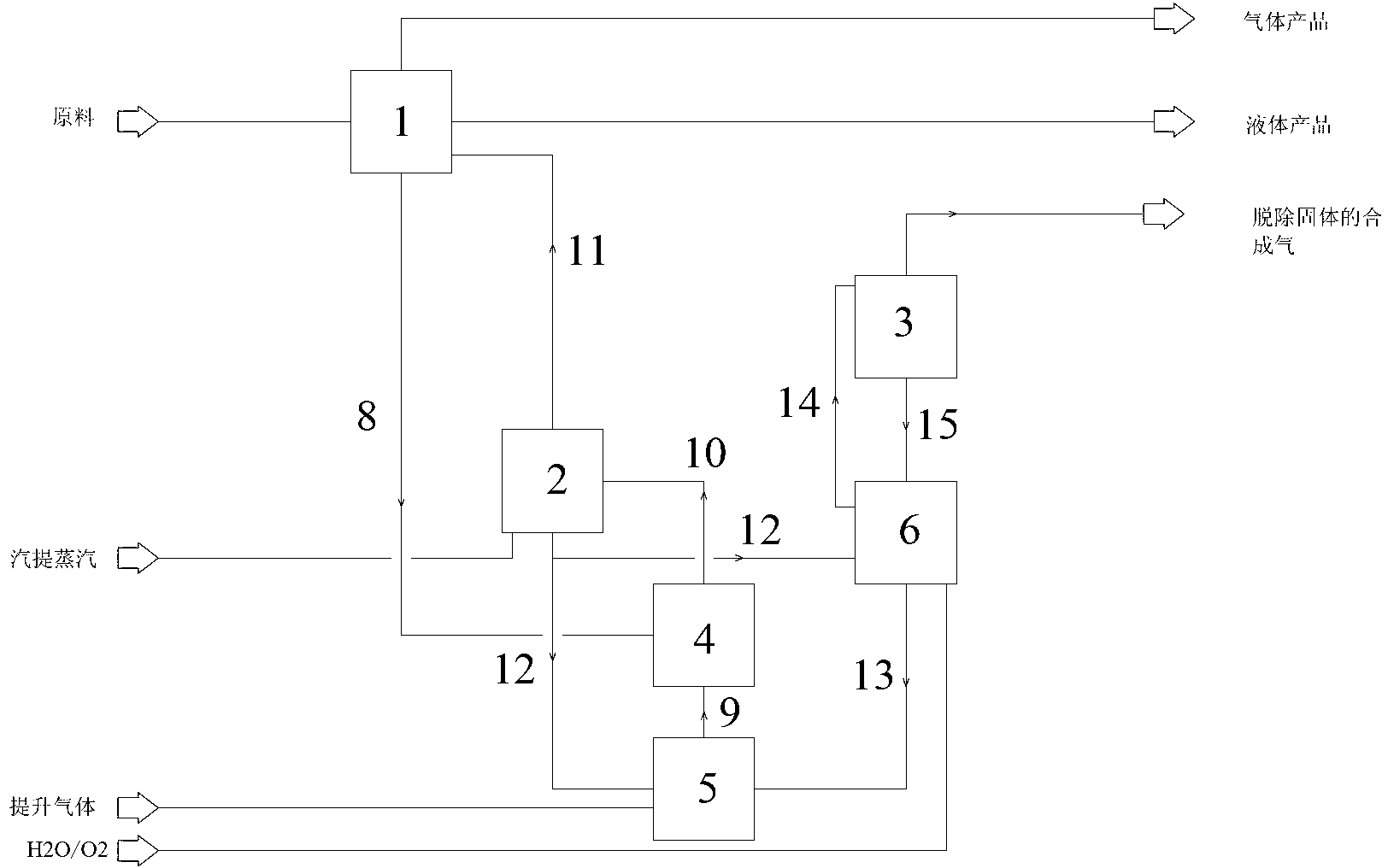
[0043] A fluidized conversion process for inferior heavy oil, its process flow is as follows figure 1 shown, including the following steps:

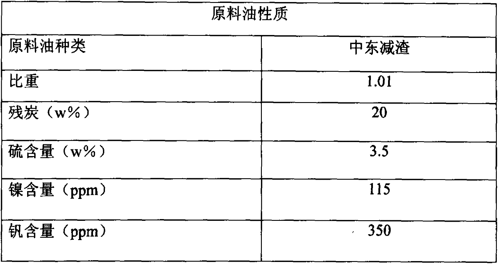
[0044] (1) The raw material oil (see Table 2 for properties) from the outside enters the lower part of the fractionation tower 1, contacts with the high-temperature reaction oil gas, separates the light components, and washes off the coke carrier and heavy components entrained in the reaction oil gas , and heated to 350°C to 400°C at the same time. After washing, the reaction oil gas enters the upper part of the fractionation tower 1 and is divided into gas and liquid products with different distillation ranges, such as dry gas, liquefied gas, gasoline fraction, diesel fraction, etc. And sent to the follow-up unit for further processing. Use the product fractionation tower to pretreat heavy raw materials, separate out the light components, and heat them, which saves equipment and heating furnaces for pretreatment of heavy oil raw materi...

Embodiment 2

[0060] Adopt the raw material and technological process identical with embodiment 1, riser reactor operating condition and product distribution are shown in Table 5:

[0061] table 5

[0062]

[0063]

[0064] The operating conditions and product distribution of the gasification reactor are shown in Table 6:

[0065] Table 6

[0066]

Embodiment 3

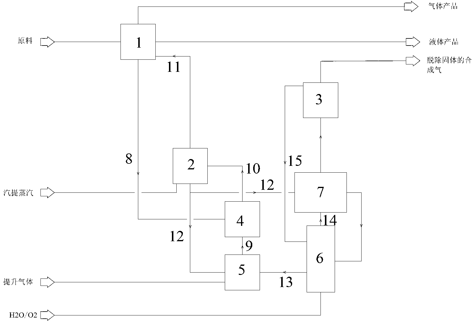
[0068] See figure 2 , the process flow is similar to that of Example 1, the difference is that in Example 3, a preheater 7 is added, which mainly plays a heating role. Preheating, while reducing the temperature of the high-temperature syngas 14, improves the operating conditions of the second gas-solid separation device 3. The operating conditions and product distribution of the gasification reactor in Example 3 are shown in Table 7.

[0069] Table 7

[0070]

[0071]


PUM

PropertyMeasurementUnit
particle diameteraaaaaaaaaa
specific surface areaaaaaaaaaaa

Abstract

The invention relates to an inferior heavy oil fluidization conversion technology. The inferior heavy oil fluidization conversion technology comprises that raw material oil is treated by a fractionating tower, then enters into a lifting pipe reactor, undergoes a contact reaction with coke carriers from a coke carrier mixer, then enters into a first gas-solid separation device and is separated; the separated reaction oil gas is fed into the fractionating tower and is subjected to product division; the coke carriers with coke is stripped and is divided into two parts, one of the two parts is fed into the coke carrier mixer, then is mixed with the high-temperature coke carriers from a vaporizer and then is fed back to the lifting pipe reactor, and other one of the two parts is fed into the vaporizer, contacts with oxygen-containing gas and water vapor and undergoes a gasification reaction; the produced synthetic gas is separated by a second gas-solid separation device, is fed into a follow-up section, and is subjected to heat recovery and conversion; and the vaporized coke carriers are fed into the coke carrier mixer and is mixed with the coke carriers with the coke. Compared with the prior art, the inferior heavy oil fluidization conversion technology has the advantages of simple process, low investment, strong raw material adaptability, good product distribution and good environmental benefits.

Description

technical field [0001] The invention relates to a heavy oil conversion process, in particular to a fluidized conversion process for inferior heavy oil. Background technique [0002] With the decrease of petroleum resources and the continuous increase of crude oil price, the trend of heavy and inferior quality is becoming more and more obvious. How to economically and effectively utilize heavy oil resources has become an important issue of concern to all countries in the world. On the other hand, the requirements for environmental protection are becoming increasingly stringent, and the demanding requirements for sulfur and nitrogen recovery have also brought huge challenges to heavy oil processing. [0003] There are two types of heavy oil processing technologies: hydrogenation and decarbonization. The hydrogenation reaction of heavy oil is more difficult to realize than gasoline and diesel hydrogenation, the equipment investment is huge, and the industrial promotion is lim...

Claims


Application Information

Patent Timeline
Patent Type & Authority Applications(China)
IPC IPC(8): C10G55/02C10J3/56C10J3/84
Inventor 张韩张涧张勇
Owner SHANGHAI HOTO PETROCHEM ENG
Why Eureka
Try Eureka