Production equipment for manufacturing excellent optical fiber preforms by VAD (vapor axial deposition) method

A technology of optical fiber preform and production equipment, which is applied in the field of optical fiber equipment, can solve problems such as uneven distribution of reaction gas, uneven dust deposition, and lower production quality of optical fiber preform, so as to ensure uniform distribution, improve production quality, and be flexible The effect of temperature control

Inactive Publication Date: 2018-03-23
南京卓茨机电科技有限公司
View PDF0 Cites 4 Cited by
  • Summary
  • Abstract
  • Description
  • Claims
  • Application Information

AI Technical Summary

Problems solved by technology

[0003] When using the VAD method to manufacture optical fiber preforms, since the position of the hydrogen-oxygen torch at the bottom of the blank is fixed, the distribution of the reaction gas around the seed rod inside the blank is uneven, resulting in the formation of silicon dioxide and The uneven deposition of germanium and other dust affects the production quality of the optical fiber preform. Not only that, there is usually an annular heater on the top of the preform to heat the outer periphery of the preform to promote the reaction. The amount of heat radiation in the same direction is equal, so that the degree of reaction inside the billet is the same. Due to the slight difference in the dust deposition around the seed rod, the uniform heating method cannot ensure the uniform dust deposition around the seed rod. Therefore, a ring heater is used. The heating reaction cannot finely adjust the periphery of the seed rod, thereby reducing the production quality of the optical fiber preform

Method used


Image

  • Production equipment for manufacturing excellent optical fiber preforms by VAD (vapor axial deposition) method
  • Production equipment for manufacturing excellent optical fiber preforms by VAD (vapor axial deposition) method
  • Production equipment for manufacturing excellent optical fiber preforms by VAD (vapor axial deposition) method

Examples


Embodiment Construction

[0024] The present invention is described in further detail now in conjunction with accompanying drawing. These drawings are all simplified schematic diagrams, which only illustrate the basic structure of the present invention in a schematic manner, so they only show the configurations related to the present invention.

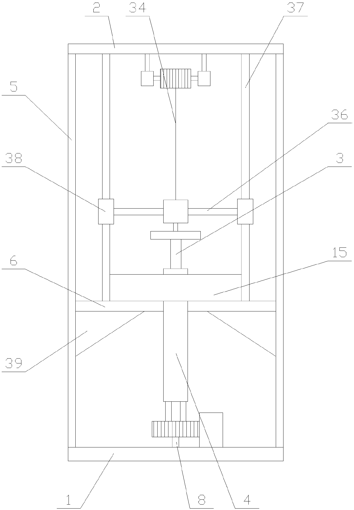
[0025] Such as figure 1 As shown, a well-manufactured optical fiber preform production equipment adopts the VAD method, including a base 1, a top plate 2, a seed rod 3, a blank rod 4, a transmission mechanism, a feeding mechanism, a heating mechanism and two supporting mechanisms. The supporting mechanisms are respectively located on both sides above the base 1, the top plate 2 is erected on the two supporting mechanisms, the feeding mechanism, the blank rod 4, the seed rod 3 and the transmission mechanism are sequentially arranged from bottom to top, and the seed The bottom end of the rod 3 is arranged in the blank rod 4, the heating mechanism is arranged on...


PUM


Abstract

The invention relates to production equipment for manufacturing excellent optical fiber preforms by a VAD (vapor axial deposition) method. The production equipment comprises a seed rod, a blank rod, atransmission mechanism, a supply mechanism, a heating mechanism and two supporting mechanisms. The supply mechanism comprises a gear, a supporting shaft, a rack, a translation unit and at least two oxyhydrogen flame blast burners. The translation unit comprises a first motor, a first connecting rod and a second connecting rod. The heating mechanism comprises a heating ring and at least two heating components, and each heating component comprises a regulating plate, an X-ray detector, a laser emitter and a regulating unit. The production equipment for manufacturing the excellent optical fiberpreforms by the VAD (vapor axial deposition) method has advantages that the supply mechanism enables the oxyhydrogen flame blast burners to rotate, reaction gas is supplied to each position at the bottom end of the blank rod, uniform attachment of dust on the outer periphery of the seed rod is benefited, heating conditions at each position of the outer periphery of the blank rod are controlled through the heating mechanism, the reaction degree at each position is controlled according to production conditions to enable uniform attachment of dust on the surface of the seed rod, and accordingly optical fiber preform production quality is improved.

Description

technical field [0001] The invention relates to the field of optical fiber equipment, in particular to a well-manufactured optical fiber preform production equipment using the VAD method. Background technique [0002] Optical fiber preforms are also called rods. The manufacturing process is the process of making silicon tetrachloride and other raw materials into preforms with the same refractive index distribution as optical fibers and a diameter of 1 to 3 cm. There are many manufacturing methods, commonly used are: MCVD method, VCD method, OVD method and PCVD method. Among them, the VCD method belongs to the external tube method, which is to send high-purity silicon tetrachloride, tetragreen germanium and other reagents into the hydrogen-oxygen flame blowtorch in a gaseous state to oxidize into ultra-fine dust such as silicon dioxide and germanium dioxide and deposit them in a rotating state. The lower end surface of the quartz glass seed rod used as the target forms a bla...

Claims


Application Information

Patent Timeline
Patent Type & Authority Applications(China)
IPC IPC(8): C03B37/014
CPCC03B37/0142C03B2201/31C03B2207/50C03B2207/60
Inventor 俞桂英
Owner 南京卓茨机电科技有限公司
Why Eureka
Try Eureka