Pressurized fluidized bed combustor with fuel cell carbon dioxide capture

A pressurized fluidized bed, fuel cell technology, applied in fluidized bed combustion equipment, fuel cells, electrochemical generators, etc., can solve problems such as increasing power costs, reduce capital costs, and improve the effects of existing technologies

Inactive Publication Date: 2019-12-17
GAS TECH INST
View PDF14 Cites 2 Cited by
  • Summary
  • Abstract
  • Description
  • Claims
  • Application Information

AI Technical Summary

Problems solved by technology

According to DOE analysis, with no CO 2 These systems increase electricity costs by approximately 75% compared to captured coal-fired power plants

Method used


Image

  • Pressurized fluidized bed combustor with fuel cell carbon dioxide capture

Examples


Embodiment Construction

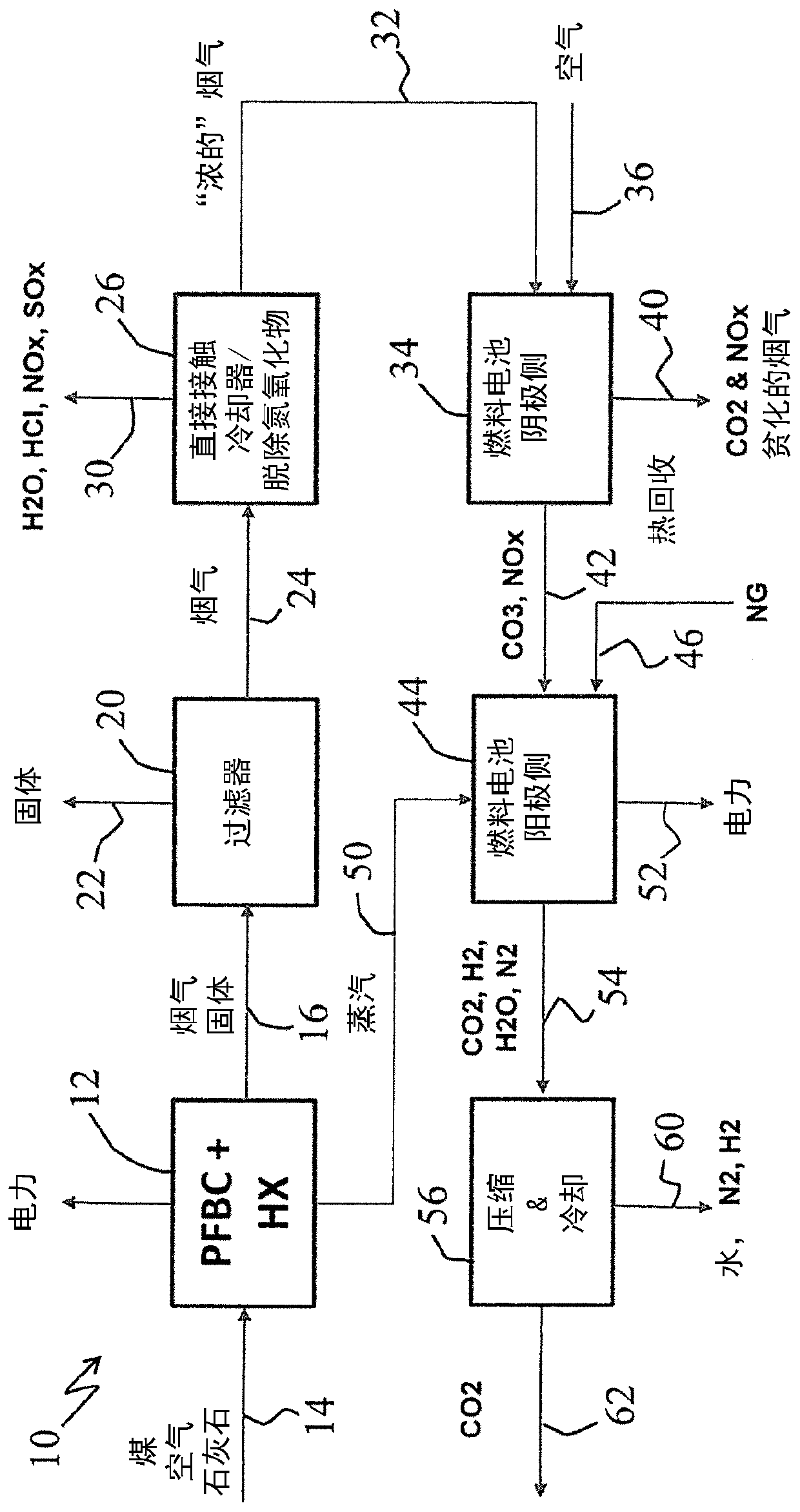
[0014] As detailed below, combining a pressurized fluidized bed combustor (PFBC) with a molten carbonate fuel cell (MCFC) is expected to provide a 2 A low-cost solution for captured power generation.

[0015] More specifically, the incorporation and use of the pressurized fluidized bed combustor (PFBC) proposed herein allows the combustion of solid fuels such as but not limited to coal, petroleum coke, biomass, etc. burn in the appliance. According to a preferred embodiment, the PFBC is approximately 1 / 3 the size of a conventional coal fired boiler at less than 1 / 2 the cost. Although an oxy-fired pressurized fluidized bed combustor, such as is currently under development, is contemplated for use in the practice of the present invention and is incorporated herein, in the following, specific reference will be made to the embodiment using an air-fired pressurized fluidized bed combustor The invention is further described, along with such air combustion operations, including and...


PUM


Abstract

Systems and methods for generating electricity that combine a pressurized fluidized bed combustor (PFBC) and a molten carbonate fuel cell (MCFC) to provide a 2 A low-cost solution for captured power generation. Introducing a solid fuel into a pressurized fluidized bed combustor to generate steam, first electricity and CO containing 2 smoke. Combining air, natural gas, at least a portion of steam and at least a portion containing CO 2 The flue gas is introduced into the molten carbonate fuel cell to generate a second electricity and mainly contains CO 2 output stream. The pressurized fluidized bed combustor may desirably be air fired and the solid fuel introduced therein may desirably be in finely divided form.

Description

[0001] Cross References to Related Applications [0002] This application claims the benefit of U.S. Provisional Patent Application Serial No. 62 / 507,398, filed May 17, 2017. The co-pending provisional application is hereby incorporated by reference in its entirety and made a part thereof, including but not limited to those parts specifically appearing below. [0003] The subject matter of this application is also related to earlier U.S. Provisional Patent Application Serial No. 61 / 184,367, filed June 5, 2009, and earlier U.S. Provisional Patent Application Serial No. 61 / 184,384, filed June 5, 2009; U.S. Provisional Patent Application Serial No. 61 / 184,382 filed June 5, 2009; Prior U.S. Provisional Patent Application Serial No. 61 / 184,383 filed June 5, 2009; Serial No. 61 / 184,383 filed June 5, 2010 Prior U.S. Patent Application Serial No. 12 / 794,218, current U.S. Patent 9,567,876, published February 14, 2017; and prior U.S. Patent Application Serial No. 15 / 085,113, filed March ...

Claims


Application Information

Patent Timeline
Patent Type & Authority Applications(China)
IPC IPC(8): C01B3/16C01B3/34
CPCF23J15/006H01M8/0643H01M2008/147H01M8/0687H01M8/0675Y02E60/50F23C10/16F23C2900/10006F23J2215/50F23J2900/15061F23C10/002F23J15/025H01M8/145
Inventor 威廉·W·福利特
Owner GAS TECH INST
Why Eureka
Try Eureka