
Vision test device

A test device and visual technology, applied in sorting and other directions, can solve the problems of reducing the detection effect, rejecting defective products, manual removal, etc., and achieve the effect of improving detection efficiency and efficient removal

Inactive Publication Date: 2019-12-20
佛山市嘉实和生物科技有限公司
View PDF1 Cites 3 Cited by
  • Summary
  • Abstract
  • Description
  • Claims
  • Application Information

AI Technical Summary

Problems solved by technology

[0002] Traditional mobile phones need to detect the graphic style, graphic size and graphic color processing of LOGO. Generally, manual detection is used for direct detection. Manual detection has the following disadvantages: low detection efficiency; high cost of detection; unstable detection results, There are artificial uncertain factors; there are situations where the staff misplaces defective products into the good product area
[0003] For this reason, Chinese utility model patent CN206235580U discloses a kind of visual testing instrument, and it comprises frame, is fixedly installed on the frame and is used for the fixture of mounting workpiece, is located at above the fixture and is fixedly installed on the tester on the frame, An alarm device fixedly installed on the frame and electrically connected to the tester and a locking device arranged next to the fixture and used to lock unqualified workpieces in the fixture (2); the locking device is electrically connected to the tester; it has a structure It is simple, easy to use, high work efficiency, low cost, stable detection quality, and avoids human factors to reduce the detection effect. However, after the detection result is output, it can only issue an alarm, and cannot automatically remove defective products. It also needs to be manually removed. , low degree of automation

Method used


Image

  • Vision test device
  • Vision test device

Examples


Embodiment Construction

[0016] The technical solutions in the embodiments of the present invention will be clearly and completely described below in conjunction with the accompanying drawings in the embodiments of the present invention. Obviously, the described embodiments are only a part of the embodiments of the present invention, rather than all the embodiments. Based on the embodiments of the present invention, all other embodiments obtained by those of ordinary skill in the art without creative work shall fall within the protection scope of the present invention.

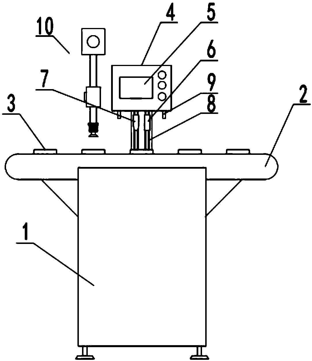
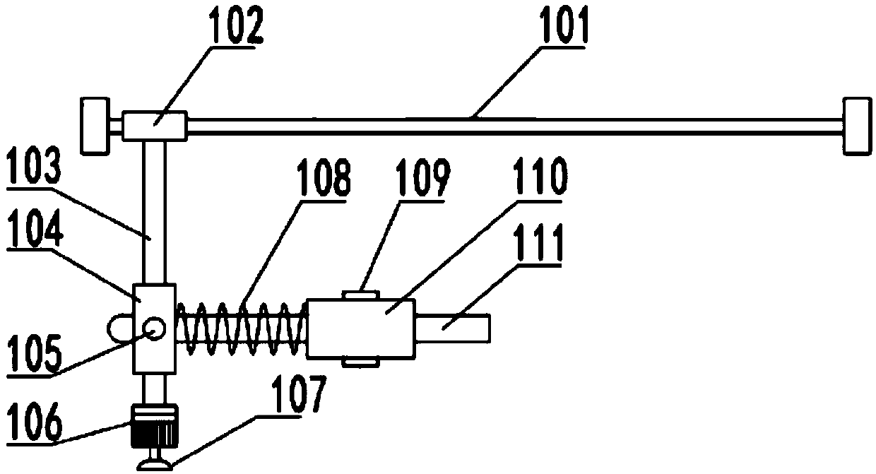
[0017] See Figure 1~2 In the embodiment of the present invention, a visual testing device includes a frame 1, a conveyor belt 2, a mobile phone positioning jig 3, a visual testing mechanism and a rejection mechanism 10. A horizontal conveyor belt 2 is installed on the frame 1, and the conveyor belt 2 is used for It is used to transport mobile phones, which is convenient for continuous detection of mobile phone LOGO. A number of position...


PUM


Abstract

The invention discloses a vision test device comprising a machine frame, a conveyor belt, mobile phone positioning clamps, a vision test mechanism and a removal device. The horizontal conveyor belt isinstalled on the machine frame. The multiple positioning clamps used for positioning mobile phones are installed on the conveyor belt. The vision test mechanism is installed at the position, corresponding to one side of the conveyor belt, of the machine frame. The removal device used for removing defective products is further installed on the machine frame. The removal device comprises a horizontal slide rod, a vertical slide rod, a telescopic cylinder and a motor. A fixed block is installed at the output end of the motor, is arranged on the outer portion of a rotation rod in a sleeving manner and is in sliding fit with the rotation rod. One end of the rotation rod is hinged to a vertical slide sleeve through a hinge shaft. The vision test device has the beneficial effects that while a vision test is conducted, the defective products can be automatically and efficiently removed according to the generated judgment result, the manual removal work does not need to be conducted by people,and the detection efficiency is greatly improved.

Description

Technical field [0001] The invention relates to a mobile phone LOGO detection mechanism, in particular to a visual test device. Background technique [0002] Traditional mobile phones need to detect the graphic style, graphic size, and graphic color processing of the LOGO. Generally, manual detection is used directly. Manual detection has the following shortcomings: low detection efficiency; high cost of detection; unstable detection results. There are man-made uncertain factors; there are situations where staff misplaced defective products into the good product area. [0003] To this end, Chinese utility model patent CN206235580U discloses a visual testing instrument, which includes a frame, a fixture fixedly mounted on the frame and used for mounting a workpiece, a tester set above the fixture and fixedly mounted on the frame, An alarm device fixedly installed on the frame and electrically connected to the tester and a locking device arranged beside the fixture and used for lock...

Claims


Application Information

Patent Timeline
Patent Type & Authority Applications(China)
IPC IPC(8): B07C5/34B07C5/36
CPCB07C5/34B07C5/362
Inventor 关瑜珠
Owner 佛山市嘉实和生物科技有限公司
Learn More