Pipe sweeping device and sweeping system

A technology for cleaning heads and pipe fittings, which is applied in the directions of cleaning hollow objects, cleaning methods and utensils, chemical instruments and methods, etc., and can solve problems such as deficiencies, complex robot structures, and the inability of cleaning balls to scrape well.

Pending Publication Date: 2019-12-20
ZHUHAI WINBASE INT CHEM TANK TERMINAL CO LTD
View PDF0 Cites 8 Cited by
  • Summary
  • Abstract
  • Description
  • Claims
  • Application Information

AI Technical Summary

Problems solved by technology

However, in this cleaning method, the spherical surface of the cleaning ball is used to scrape the inner wall of the pipe to achieve the purpose of cleaning, but the cleaning ball is easily resisted by the protruding dirt blocks that are too hard, and the problem of the cleaning ball being stuck often occurs during cleaning. In this case, a higher pressure fluid is usually used to flush away the scale or force the cleaning ball to squeeze through the scale, but the higher pressure fluid is likely to cause damage to the structure of the pipe fittings, and at the same time increase the cost
At the same time, when the dirt block is squeezed or the inner wall of the pipe fitting suddenly becomes larger, the entire cleaning ball cannot scrape the dirt inside the pipe fitting well, resulting in unclean cleaning
[0004] For this reason, some companies have designed some automatic cleaning robots in view of the above-mentioned problems that the cleaning balls are easy to get stuck and insufficient cleaning, and use these automatic cleaning robots to walk in the pipe fittings to achieve cleaning, but the structure of such robots is complicated. , the manufacturing cost is high, and the complex environment inside the pipe fittings is easy to force the entire cleaning robot to fail, which leads to the cleaning efficiency

Method used


Image

  • Pipe sweeping device and sweeping system
  • Pipe sweeping device and sweeping system
  • Pipe sweeping device and sweeping system

Examples


Embodiment Construction

[0024] This part will describe the specific embodiment of the present invention in detail, and the preferred embodiment of the present invention is shown in the accompanying drawings. Each technical feature and overall technical solution of the invention, but it should not be understood as a limitation on the protection scope of the present invention.

[0025] In the description of the present invention, it should be understood that the orientation descriptions, such as up, down, front, back, left, right, etc. indicated orientations or positional relationships are based on the orientations or positional relationships shown in the drawings, and are only In order to facilitate the description of the present invention and simplify the description, it does not indicate or imply that the device or element referred to must have a specific orientation, be constructed and operated in a specific orientation, and thus should not be construed as limiting the present invention.

[0026] I...


PUM


Abstract

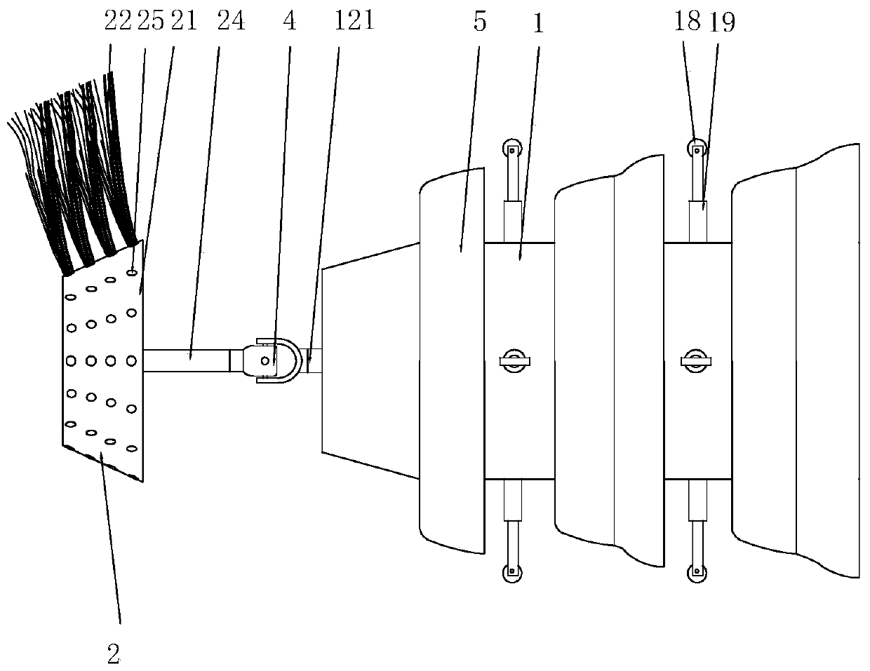
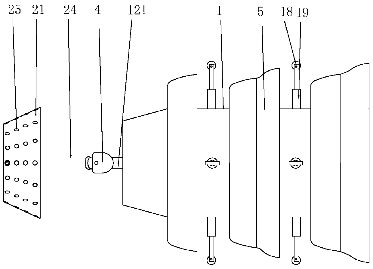
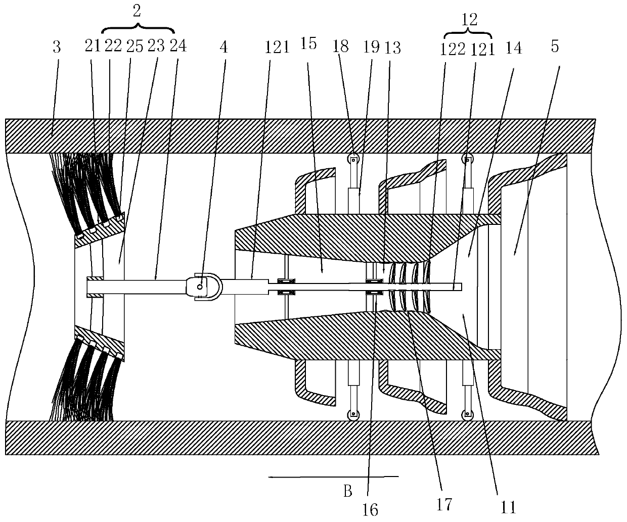
The invention discloses a pipe sweeping device. The pipe sweeping device comprises a propeller and a sweeping head, wherein a backswept-shape conical ring sleeve is arranged on the side wall of the outer ring of the propeller, and the outer edge of the conical ring sleeve can be attached to the inner wall of a pipe fitting; the sweeping head can rotate in the axial direction of the sweeping head so as to sweep the inner wall of the pipe fitting; a flow passing channel is arranged on the propeller, a rotating mechanism is rotatably arranged in the flow passing channel, and the output end of therotating mechanism is movably penetrate through the flow passing channel, is located at one end of the sweeping direction, and is connected with the sweeping head through a universal structure; and when fluid in the pipe fitting passes through the flow passing channel, the fluid can drive the rotating mechanism to rotate, and the rotating mechanism drives the sweeping head to sweep the inner wallof the pipe fitting. According to the pipe sweeping device and the sweeping system, the sweeping head can be forced to automatically rotate and sweep the inner wall of the pipe fitting while the fluid is utilized to drive the whole device to move in the pipe fitting, the structure is simple, and the sweeping effect is good.

Description

technical field [0001] The invention relates to the field of cleaning equipment for petrochemical pipe fittings, in particular to a pipe cleaning device and a cleaning system. Background technique [0002] For petrochemical storage factories, the transportation pipeline is the carrier connecting the storage tank and the tank truck, the storage tank and the wharf ship. After the material is transported in the pipeline for a period of time, a certain scaling layer is easily formed on the inner wall of the pipeline, making the pipeline through Decrease gradually, thereby reducing the amount of material conveyed. [0003] In order to protect material quality, reduce friction and prolong the service life of the pipeline, the pipeline must be pigged regularly. The traditional cleaning method is to use the cleaning ball matched with the inner wall of the pipe to pass into the housekeeper to sweep the line, and pressurized fluid such as nitrogen or water drives the soft propeller t...

Claims


Application Information

Patent Timeline
Patent Type & Authority Applications(China)
IPC IPC(8): B08B9/053B08B9/055
CPCB08B9/053B08B9/055
Inventor 陈子红
Owner ZHUHAI WINBASE INT CHEM TANK TERMINAL CO LTD
Why Eureka
Try Eureka