Lamp pole bending equipment

A technology for equipment and light poles, which is applied in the field of light pole bending equipment, can solve the problems of steel plate indentation and bending, inability to guarantee, etc., and achieve the effect of avoiding defective products and simple equipment structure.

Active Publication Date: 2019-12-20
HANGZHOU UG PHOTOELECTRIC
View PDF6 Cites 2 Cited by
  • Summary
  • Abstract
  • Description
  • Claims
  • Application Information

AI Technical Summary

Problems solved by technology

[0002] The light pole bending equipment is used to bend the steel plate into a polygonal shape, but the existing light pole bending equipment will flip the steel plate upwards and then fall under the action of the stamping force after each bending, so the falling cannot be guaranteed Keep parallel with the pressure plate 7 again, so that the oblique pressure may appear to bend the indentation of the steel plate, so as to make a qualified light pole

Method used


Image

  • Lamp pole bending equipment
  • Lamp pole bending equipment
  • Lamp pole bending equipment

Examples


Embodiment Construction

[0020] In order to enable those skilled in the art to better understand the solutions of the present invention, the technical solutions in the embodiments of the present invention will be clearly and completely described below in conjunction with the drawings in the embodiments of the present invention.

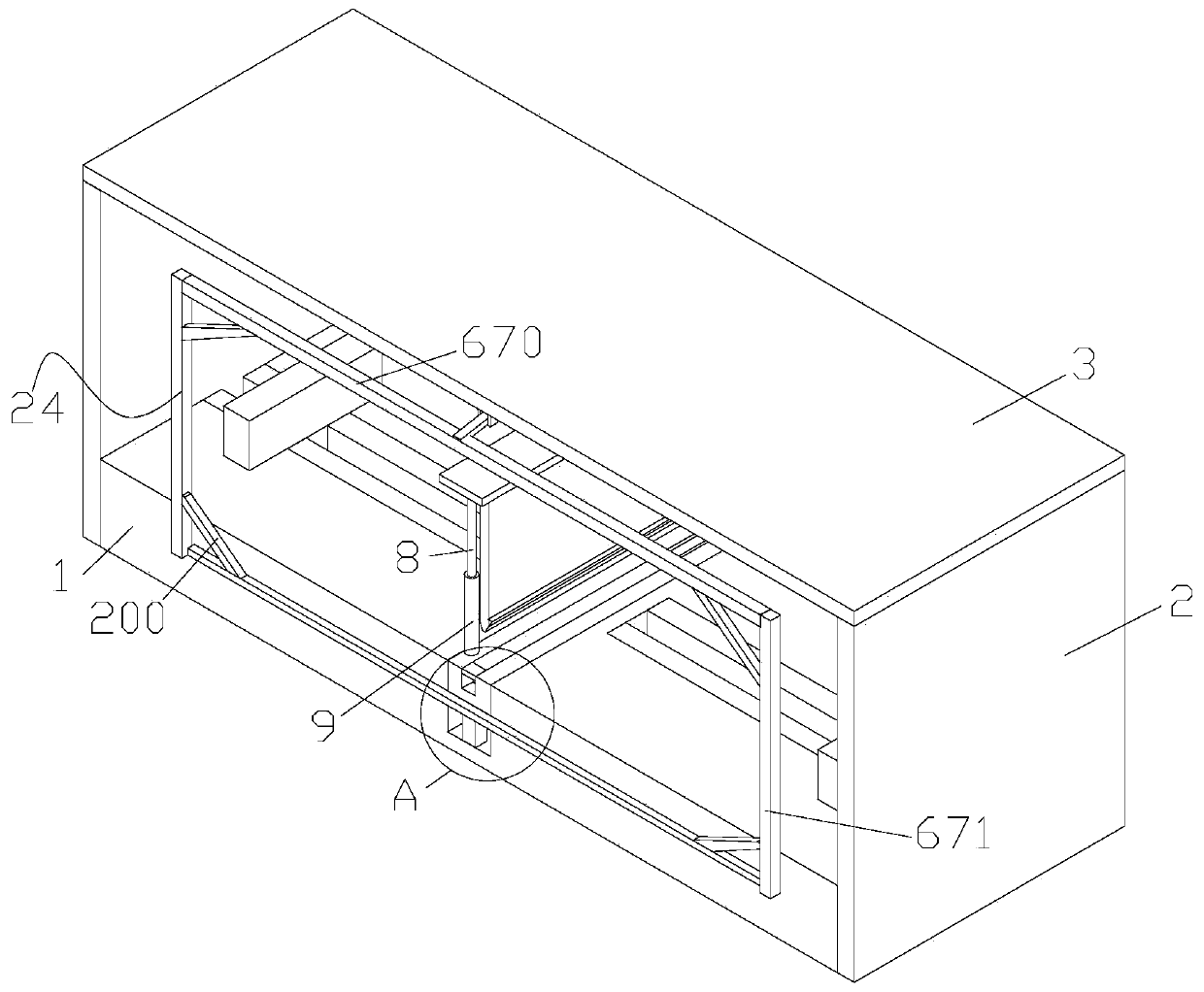
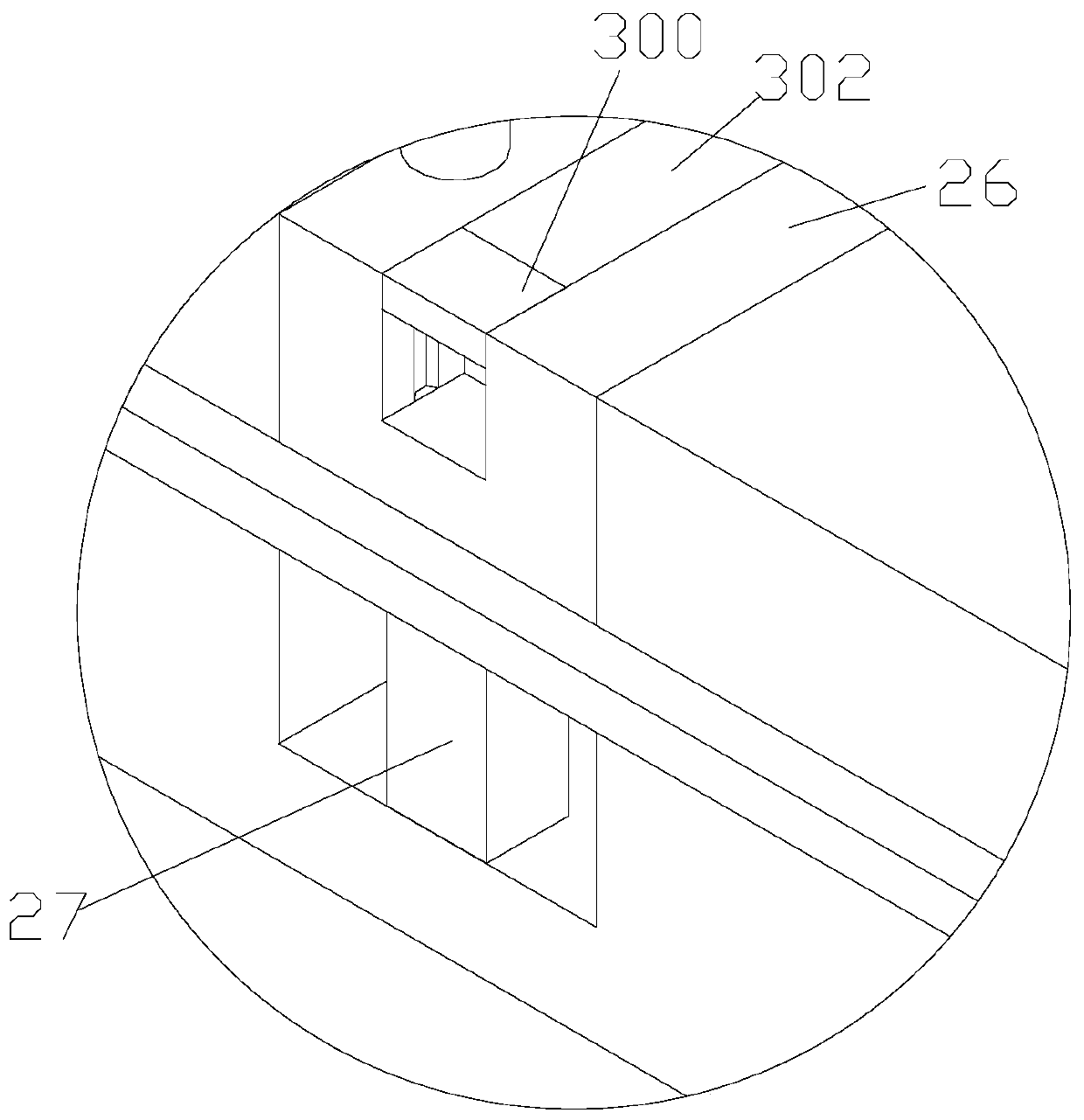
[0021] like Figure 1-6 As shown, in order to achieve the above purpose, the present invention adopts the following technical solutions: a light pole bending equipment, including a machine base 1, two vertical plates 2 fixedly arranged on the left and right end faces of the machine base 1, fixedly arranged on the two vertical plates 2 The top plate 3 on the upper end surface, the groove arranged on the upper surface of the machine base 1, the two stroke grooves respectively arranged on the left and right sides of the groove, the rodless cylinder 4 fixedly arranged in the stroke groove, the rodless cylinder 4 fixedly arranged at the output end of the rodless cylinder 4 The mov...


PUM


Abstract

The invention discloses lamp pole bending equipment. The lamp pole bending equipment comprises an engine base, two stand plates fixedly arranged on the left end face and the right end face of the engine base correspondingly, a top plate fixedly arranged on the upper end faces of the two stand plates, a groove formed in the upper surface of the engine base, two stroke grooves formed in the left side and the right side of the groove correspondingly, rodless cylinders fixedly arranged in the stroke grooves, movable plates fixedly arranged at the output ends of the rodless cylinders, an adjustingdevice arranged in the groove, a jacking device arranged on the adjusting device, and a disconnecting device arranged on the rear side of the engine base. The adjusting device comprises two first hydraulic cylinders fixedly arranged on the lower end walls of the top plates correspondingly, a lifting plate fixedly arranged at the lower ends of the first hydraulic cylinders, and a pressing plate fixedly arranged on the lower end face of the lifting plate.

Description

technical field [0001] The invention belongs to the field of light pole bending, and in particular relates to light pole bending equipment. Background technique [0002] The light pole bending equipment is used to bend the steel plate into a polygonal shape, but the existing light pole bending equipment will flip the steel plate upwards and then fall under the action of the stamping force after each bending, so the falling cannot be guaranteed Keep parallel with the pressure plate 7 again, so that the oblique pressure phenomenon may occur to bend the indentation of the steel plate, so as to make a qualified light pole. Contents of the invention [0003] In order to overcome the deficiencies of the prior art, the present invention provides a light pole bending device. [0004] In order to achieve the above purpose, the present invention adopts the following technical solutions: a light pole bending equipment, including a machine base, two vertical plates fixed on the left ...

Claims


Application Information

Patent Timeline
Patent Type & Authority Applications(China)
IPC IPC(8): B21D5/01B21D43/00
CPCB21D5/002B21D5/01
Inventor 翁小佩李耀
Owner HANGZHOU UG PHOTOELECTRIC
Why Eureka
Try Eureka