Constant-flow automatic pouring system for iron alloy casting operation

An automatic pouring and operation technology, which is applied in the control of molten metal pouring from ladles, casting equipment, metal processing equipment, etc., can solve the problems of low casting efficiency and poor automation, and achieve convenient installation/disassembly and save manpower The effect of reasonable labor and structural design

Active Publication Date: 2019-12-20
HARBIN BOSHI AUTOMATION
View PDF8 Cites 1 Cited by
  • Summary
  • Abstract
  • Description
  • Claims
  • Application Information

AI Technical Summary

Problems solved by technology

[0008] The invention aims to solve the problem of low casting efficiency caused by poor continuity and automation of existing ladle casting

Method used


Image

  • Constant-flow automatic pouring system for iron alloy casting operation
  • Constant-flow automatic pouring system for iron alloy casting operation
  • Constant-flow automatic pouring system for iron alloy casting operation

Examples


specific Embodiment approach 1

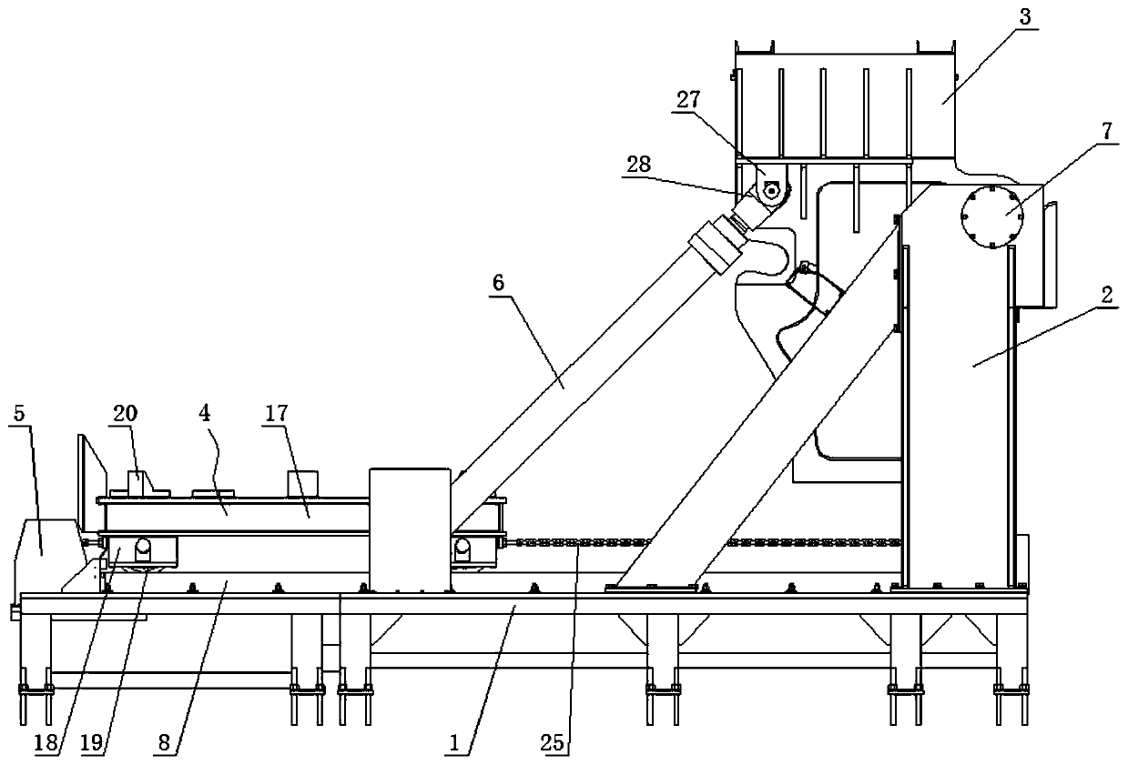
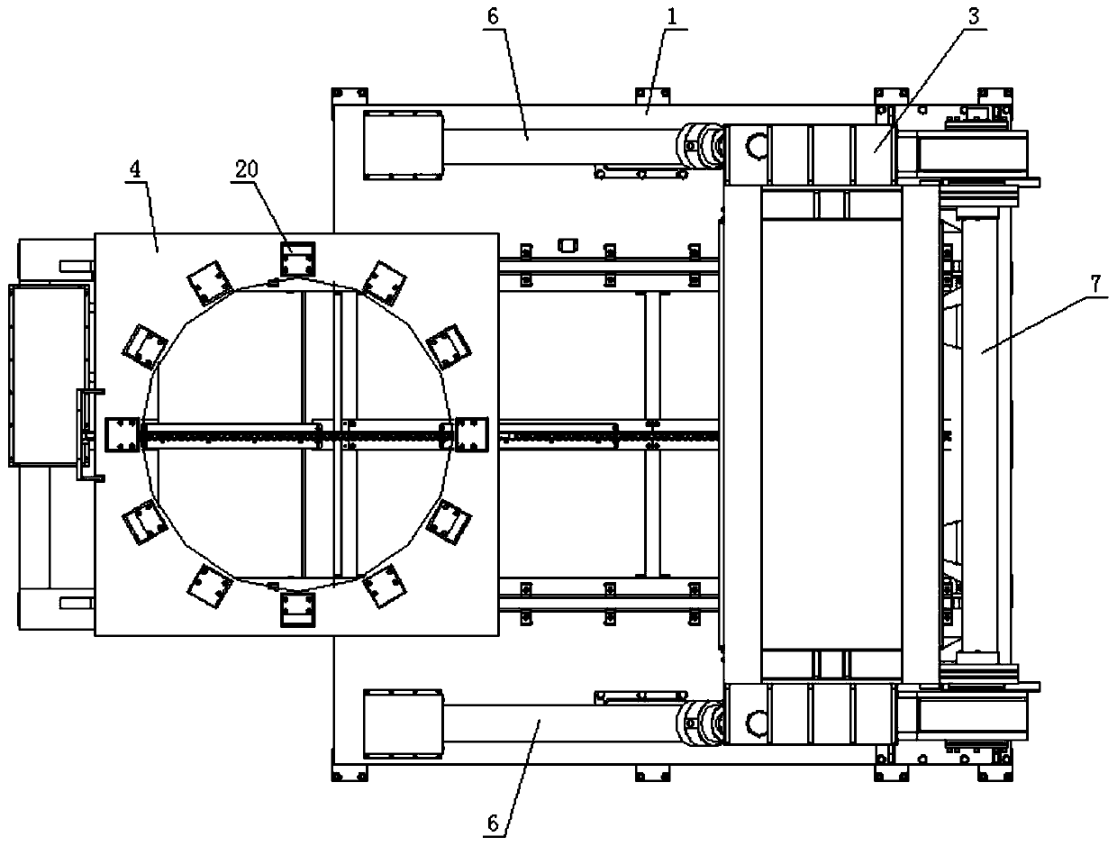
[0034] Specific implementation mode one: combine Figure 1-Figure 9 Describe this embodiment, a constant-flow automatic pouring system used in ferroalloy casting operations in this embodiment, including a frame 1, a door frame 2, a dumping device 3, a ladle car 4, a driving mechanism 5, and a hydraulic cylinder 6, and the frame 1 and door frame 2 are made of high-strength steel tailor welding, and the bottom of frame 1 is fixed on the ground through anchor bolts / embedded bolts. This fixing method has a good fixing effect, and door frame 2 is fixedly installed on the frame 1, the cylinder end of the hydraulic cylinder 6 is installed on the frame 1, the output end of the hydraulic cylinder 6 is hingedly installed with the dumping device 3, and the dumping device 3 is hingedly installed on the door frame 2 through the rotating shaft 7, and the installation methods are two , one of which is that bearing seats are respectively installed on both sides of the door frame 2, and the ro...

specific Embodiment approach 2

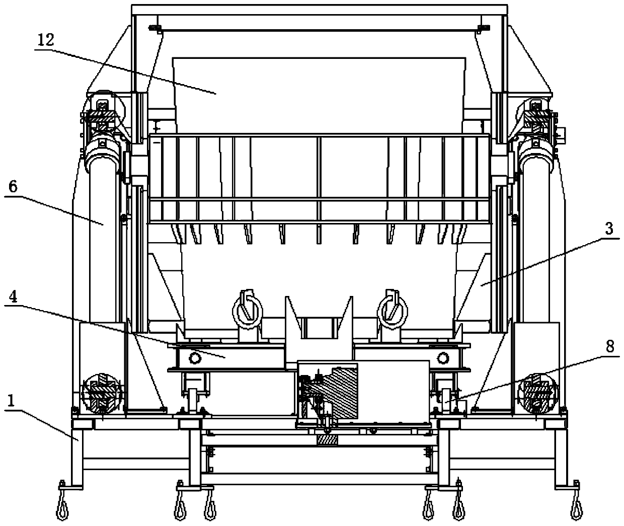
[0035] Specific implementation mode two: combination Figure 1-Figure 9 This embodiment is described. In this embodiment, a constant-flow automatic pouring system used in ferroalloy casting operations, the cylinder body end of the hydraulic cylinder 6 is installed on the frame 1, and the output end of the hydraulic cylinder 6 is hingedly installed with the dumping device 3. The dumping device 3 is hingedly mounted on the door frame 2 through the rotating shaft 7, the dumping device 3 includes a supporting plate 10 and a surrounding plate 11, the surrounding plate 11 is installed on the supporting plate 10, the surrounding plate 11 has an open end, and the surrounding plate 11 and the supporting plate The accommodation space composed of 10 is used to accommodate the steel ladle 12, and the ear plate 13 is installed on the coaming plate 11, and the dumping device 3 is established and installed with the rotating shaft 7 through the ear plate 13; At this time, the ladle car 4 tran...

specific Embodiment approach 3

[0036] Specific implementation mode three: combination Figure 1-Figure 9Describe this embodiment, a constant flow automatic pouring system used in ferroalloy casting operations in this embodiment, the bayonet 14 is processed on the coaming plate 11, and the outer wall of the ladle 12 is formed by tailor welding of steel plates 15. The skirt part 15 enhances the structural strength of the steel ladle 12. Two lifting lugs 16 are welded on the side wall of the steel ladle 12. When dumping, the package body of the steel ladle 12 fits with the supporting plate 10 of the dumping device 3, and the supporting plate 10 is used For supporting the ladle 12 , the lug 16 of the ladle 12 fits with the bayonet 14 of the dumping device 3 , and the bayonet 14 is used to locate the installation position of the steel ladle 12 on the dumping device 3 . In this embodiment, the supporting plate 10 of the dumping device is used to support the steel ladle 12, and the buckle 14 fits with the lifting ...


PUM


Abstract

The invention discloses a constant-flow automatic pouring system for iron alloy casting operation, and belongs to the field of metal smelting equipment. The system aims to solve the problem that the casting efficiency is low due to the fact that the existing steel ladle casting continuity and the automatic property are poor. The system comprises a machine frame, a gantry, a pouring device, a ladlecar, a drive mechanism and a hydraulic cylinder, wherein the gantry is fixedly arranged on the machine frame, the pouring device is arranged on the gantry through a rotating shaft in a hinge joint mode, the cylinder end of the hydraulic cylinder is arranged on the machine frame, an output end of the hydraulic cylinder is hinged to the pouring device, under the driving of the hydraulic cylinder, the pouring device rotates around the rotating shaft, two parallel guide rails are arranged on the machine frame, the ladle car is arranged on the guide rails, the ladle car is used for bearing ladles,the driving mechanism is arranged on the machine frame, the driving mechanism is matched and installed with the ladle car, and the driving mechanism drives the ladle car to achieve linear reciprocating motion on the guide rails. The system has the advantages of high mechanization degree and good continuous pouring quality effect, and is suitable for popularization and use.

Description

technical field [0001] The invention relates to an automatic dumping device, which belongs to the field of metal smelting equipment. Background technique [0002] The final product of the smelting industry, ingots are manufactured by pouring molten metal into permanent or reusable molds. After solidification, these ingots (or bars, slabs or billets, depending on the container) are further machined into a variety of new shapes. [0003] At present, the casting of molten steel in steel mills is often one-time slow casting, which requires personnel to operate the crane, visually inspect the opening of the casting pool, and use the crane hook to pick up the ladle to realize the pouring of the steel water; Fixture, the steel ladle is installed on the fixture, and then the spreader is used to turn the fixture and the ladle together to realize the ladle casting operation; but these existing casting methods have the following disadvantages: [0004] 1. Using the crane to overturn ...

Claims


Application Information

Patent Timeline
Patent Type & Authority Applications(China)
IPC IPC(8): B22D37/00
CPCB22D37/00
Inventor 吴明月王录张洋刘延杰奚泉李婉辰
Owner HARBIN BOSHI AUTOMATION
Why Eureka
Try Eureka