
Interface chip assembling mechanism of electronic product

A technology of electronic products and assembly mechanism, which is applied in the field of electronic product processing equipment, and can solve the problems of a large amount of manpower and low assembly efficiency

Inactive Publication Date: 2019-12-20
DONGGUAN RONGGONG AUTOMATION TECH CO LTD
View PDF0 Cites 3 Cited by
  • Summary
  • Abstract
  • Description
  • Claims
  • Application Information

AI Technical Summary

Problems solved by technology

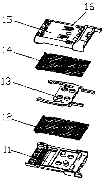
[0002] like figure 2 As shown, it is an exploded view of an interface core of an electronic product. During the assembly process, the lower terminal 12 needs to be put into the lower case 11 first, and then the clamping block 3 is installed. The clamping block has four holes, two of which are The first hole is passed through by the mounting post on the lower case, and the other two holes are passed through by the two mounting posts on the upper case 15. After the clamping block is installed, the upper terminal 14 is installed. It is better to install the upper case 15 and pass through The mounting columns and mounting holes of the upper and lower shells cooperate with each other to realize the clamping of the upper and lower shells. The outer sides of the upper shell 15 and the lower shell 11 are provided with shrapnel 16 for inserting into the product shell. Most of the existing assembly is manual assembly. Sometimes semi-automatic assembly is also carried out with some equipment such as conveyor belts. The overall assembly efficiency is not high, and several stations require a lot of manpower

Method used


Image

  • Interface chip assembling mechanism of electronic product
  • Interface chip assembling mechanism of electronic product
  • Interface chip assembling mechanism of electronic product

Examples


Embodiment Construction

[0024] In order to enable those skilled in the art to better understand the technical solution of the present invention, the present invention will be described in detail below in conjunction with the accompanying drawings. The description in this part is only exemplary and explanatory, and should not have any limiting effect on the protection scope of the present invention. .

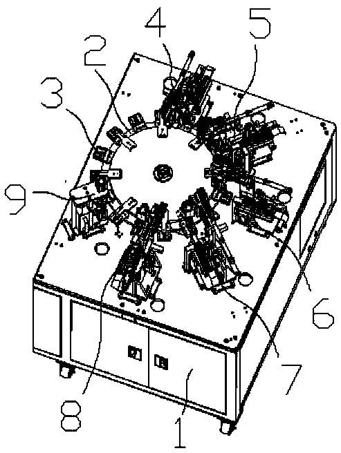
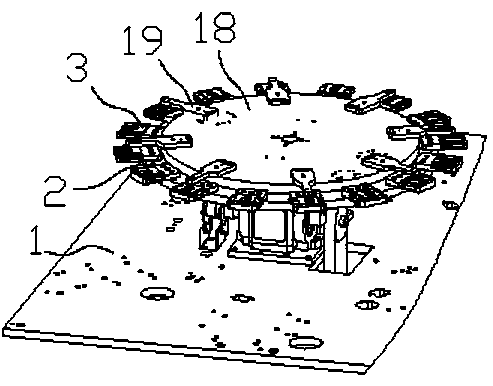
[0025] Such as Figure 1-6 As shown, the specific structure of the present invention is: an interface core assembly mechanism for electronic products, including a frame 1, the frame 1 is provided with a turntable 2 with a driving structure, and the turntable 2 is uniformly arranged There is a set of loaders 3, the set of loaders 3 includes a carrier body 23, the carrier body 23 is provided with a loading port 24 with a width consistent with the length of the lower shell 11, and the bottom surface of the loading port 24 is opened There are shrapnel grooves 25 positioned to match the shrapnel 16 and hea...


PUM


Abstract

The invention relates to an interface chip assembling mechanism of an electronic product. The interface chip assembling mechanism of the electronic product comprises a machine frame. A rotating disk with a drive structure is arranged on the machine frame. The rotating disk is evenly provided with assembling carriers. Each assembling carrier comprises a carrier body. Each carrier body is provided with a material loading opening with the width equal to the length of a lower shell. The bottom face of each material loading opening is provided with an elastic sheet groove matched with an elastic sheet in position and a head matching groove matched with the head of the lower shell in position and shape. The two side faces of the innermost end of each material loading opening are provided with aninclined opening facilitating assembling and a terminal matching opening matched with a terminal correspondingly. The machine frame is sequentially provided with a lower shell feeding device, a lowerterminal feeding device, a clamping block feeding device, an upper terminal feeding device, an upper shell feeding device and a pressing device in the rotation direction of the rotating disk, and thelower shell feeding device, the lower terminal feeding device, the clamping block feeding device, the upper terminal feeding device, the upper shell feeding device and the pressing device are matchedwith the assembling carriers. By means of the structural design of the assembly carriers, the lower shell can be stably placed, the rotating disk cooperates with the feeding devices of all the parts,and then continuous automatic assembly of the interface chip is achieved; and in this way, the assembly efficiency is improved, and work intensity of workers is lowered.

Description

technical field [0001] The invention relates to the field of electronic product processing equipment, in particular to an interface core assembly mechanism for electronic products. Background technique [0002] Such as figure 2 As shown, it is an exploded view of an interface core of an electronic product. During the assembly process, the lower terminal 12 needs to be put into the lower case 11 first, and then the clamping block 3 is installed. The clamping block has four holes, two of which are The first hole is passed through by the mounting post on the lower case, and the other two holes are passed through by the two mounting posts on the upper case 15. After the clamping block is installed, the upper terminal 14 is installed. It is better to install the upper case 15 and pass through The mounting columns and mounting holes of the upper and lower shells cooperate with each other to realize the clamping of the upper and lower shells. The outer sides of the upper shell 15 ...

Claims


Application Information

Patent Timeline
IPC IPC(8): B23P21/00
CPCB23P21/006
Inventor 赵昌文
Owner DONGGUAN RONGGONG AUTOMATION TECH CO LTD
Learn More