A fully automatic pedal assembly machine for automobiles

A fully automatic, assembly machine technology, applied in the direction of assembly machines, metal processing equipment, metal processing, etc., can solve the problems of difficult assembly, inability to achieve high efficiency, mass production, etc., and achieve the effect of satisfying high efficiency

Active Publication Date: 2021-09-28
SHYE CHAN FUJIAN MECHANICAL INDAL
View PDF7 Cites 0 Cited by
  • Summary
  • Abstract
  • Description
  • Claims
  • Application Information

AI Technical Summary

Problems solved by technology

Since the assembly of the pedal inner sleeve d and the bushing c is a transition fit, the gap between the pedal inner sleeve d and the bushing c is extremely small, and the coaxiality between the pedal inner sleeve d and the bushing c needs to be precisely controlled during assembly. It is difficult to assemble with equipment, so the traditional assembly of the inner casing of the pedal needs to be manually assembled by the operator to ensure the accuracy of the assembly, so high-efficiency and mass production cannot be achieved

Method used


Image

  • A fully automatic pedal assembly machine for automobiles
  • A fully automatic pedal assembly machine for automobiles
  • A fully automatic pedal assembly machine for automobiles

Examples


Embodiment 1

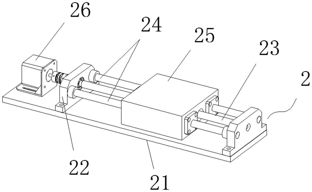
[0034] Such as figure 2 As shown, the sliding table mechanism 2 includes a sliding table bottom plate 21, a sliding table mounting seat 22 is fixed on both sides of the top surface of the sliding table bottom plate 21, and a sliding table screw rod 23 is arranged between the sliding table mounting seats 22 on both sides and symmetrically arranged. The guide slide bar 24 on both sides of the slide table screw rod 23, the two ends of the slide table screw rod 23 and the slide table mounting seat 22 are installed through bearing rotation, the two ends of the guide slide bar 24 are fixedly installed with the slide table mounting seat 22, and the two sides slide A mobile platform 25 is arranged between the platform mounting bases 22, and the sliding platform screw rod 23 and the guide slide bar 24 are screwed and slidably connected with the mobile platform 25 respectively. Inner nut sleeve, guide slide bar 24 and movable table 25 side joints are embedded with linear bearings, one ...

Embodiment 2

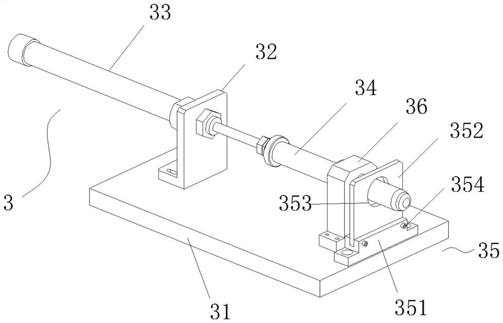
[0036] Such as image 3 As shown, the guide rod baffle plate mechanism 3 includes an installation base plate 31, the top side of the installation base plate 31 is equipped with a guide rod cylinder 33 through a guide rod cylinder seat 32, and the telescopic end of the guide rod cylinder 33 is equipped with a guide rod 34, and the guide rod 34 It is a cylinder, and the front end of the guide rod 34 is a round head structure, which is convenient to penetrate into the inner cavity of the inner sleeve of the pedal. A linear bearing seat 36 is installed between and close to the side of the baffle plate assembly 35. The front end of the guide rod 34 runs through the linear bearing seat 36 and the baffle plate assembly 35 in turn, and is slidably connected with the linear bearing seat 36. The setting of the linear bearing seat 36 ensures The guide rod 34 telescopically moves along its axis;

[0037]The baffle plate assembly 35 comprises a baffle plate inserting block 351, and the to...

Embodiment 3

[0040] Such as Figure 4 As shown, the support part and the positioning part in the support positioning mechanism 4 are distributed at intervals before and after, the support part includes a support block 41, and the top of the support block 41 is provided with a pedal rod limit groove 42, and the top of the support block 41 is perpendicular to the pedal rod limit. The direction of the position groove 42 is provided with the jaw relief groove 43, and the positioning part comprises the I-shaped support seat 44, and the top of the I-shaped support seat 44 is equipped with a positioning block 45, and the top of the positioning block 45 is provided with a positioning arc groove 46, and the positioning The top of the block 45 is perpendicular to the positioning arc groove 46 and is provided with a pedal rod give way groove 47. After the pedal is placed, its rod is fixed by cooperating with the pedal rod limit groove 42. The fixed sleeve at the front end and the positioning arc groov...


PUM


Abstract

The invention discloses a fully automatic automobile pedal assembly machine in the technical field of pedal assembly machines. mechanism, the guide rod baffle mechanism is installed on the top of the moving end of the slide mechanism, the guide rod baffle mechanism includes a baffle for resisting the inner sleeve of the pedal and a guide rod for guiding the inner sleeve of the pedal, The supporting and positioning mechanism includes a supporting part for supporting the main body of the pedal and a positioning part for positioning the front end of the pedal. The push rod assembled by the casing, the invention provides a fully automatic pedal assembly machine for automobiles, the device can realize the continuous automatic assembly of the inner casing of the pedal and the pedal, and can meet high-efficiency and mass production.

Description

technical field [0001] The invention relates to the technical field of pedal assembly machines, in particular to a pedal assembly machine for fully automatic vehicles. Background technique [0002] Such as Figure 7 In the car pedal shown, the end of the connecting rod a has a structure of a fixed sleeve b, and the two ends of the inner cavity of the fixed sleeve b are provided with a bushing c, and an inner sleeve d of the pedal passes through the bushes c at both ends. Through and assembled in the fixed sleeve b, when the pedal is working, the fixed sleeve b and the bushing c rotate around the inner sleeve d of the pedal. Since the assembly of the pedal inner sleeve d and the bushing c is a transition fit, the gap between the pedal inner sleeve d and the bushing c is extremely small, and the coaxiality between the pedal inner sleeve d and the bushing c needs to be precisely controlled during assembly. It is difficult to assemble with equipment, so the traditional assembly...

Claims


Application Information

Patent Timeline
Patent Type & Authority Patents(China)
IPC IPC(8): B23P21/00
CPCB23P19/006B23P21/002
Inventor 林松林
Owner SHYE CHAN FUJIAN MECHANICAL INDAL
Why Eureka
Try Eureka