
Automatic device used for assembling component provided with magnetic ring

A technology of automation equipment and assembly belts, which is applied to assembly machines, metal processing equipment, manufacturing tools, etc., can solve problems such as delays in assembly progress, inability to load magnetic rings, slow assembly efficiency, etc., to achieve high assembly efficiency and save energy. Labor costs, the effect of reducing the number of staff

Inactive Publication Date: 2019-12-20
东莞明控自动化有限公司
View PDF5 Cites 2 Cited by
  • Summary
  • Abstract
  • Description
  • Claims
  • Application Information

AI Technical Summary

Problems solved by technology

[0002] Because the magnetic ring is magnetic, the currently commonly used feeding equipment is a vibrating feeding device, but the vibrating plate of the vibrating feeding device is generally made of metal, which will generate suction with the magnetic ring, and the magnetic ring cannot be realized by the vibrating feeding device. Feeding, and when a large number of magnets pour in, the two adjacent magnetic rings will attract each other, but the current feeding device cannot separate the two adjacent magnetic rings, and it is impossible to realize the magnetic rings one by one In addition, at present, when assembling parts with magnetic rings, manual assembly is required, and the assembly efficiency is low. In addition, during the long-term assembly process, work fatigue is prone to occur, resulting in a further slowdown in assembly assembly efficiency, and even parts assembly errors. The phenomenon of reassembly, delaying the assembly progress

Method used


Image

  • Automatic device used for assembling component provided with magnetic ring
  • Automatic device used for assembling component provided with magnetic ring
  • Automatic device used for assembling component provided with magnetic ring

Examples


Embodiment Construction

[0038] In order to facilitate the understanding of those skilled in the art, the present invention will be further described below in conjunction with the examples, and the contents mentioned in the embodiments are not intended to limit the present invention.

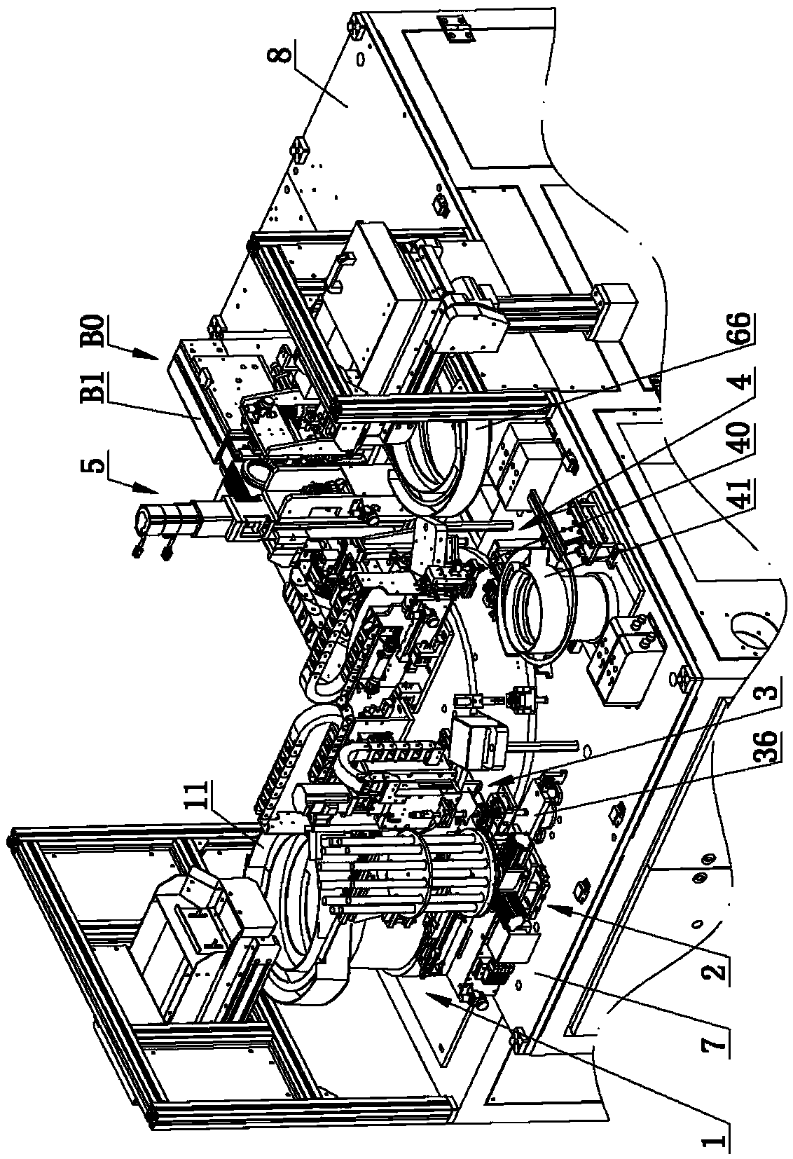
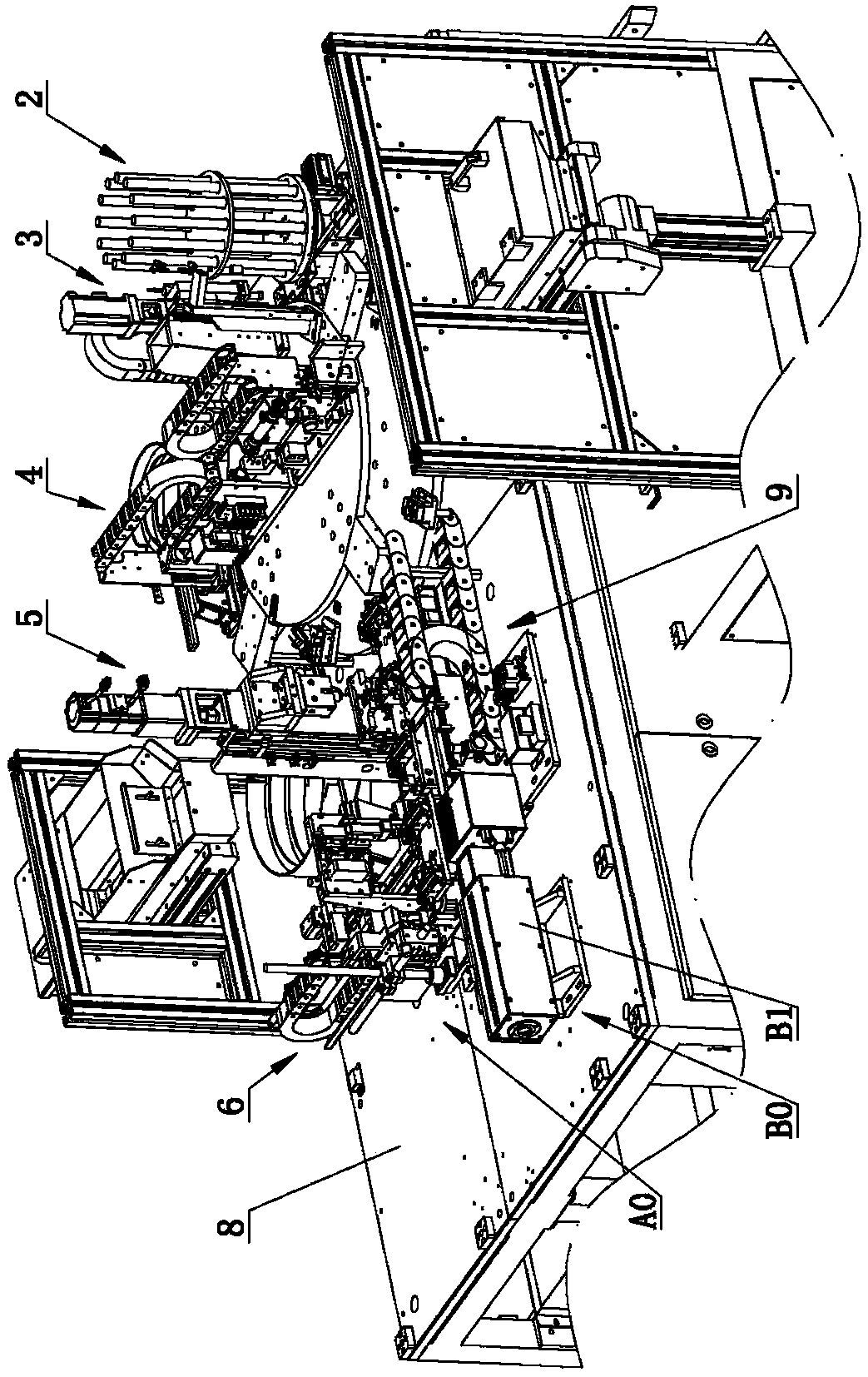
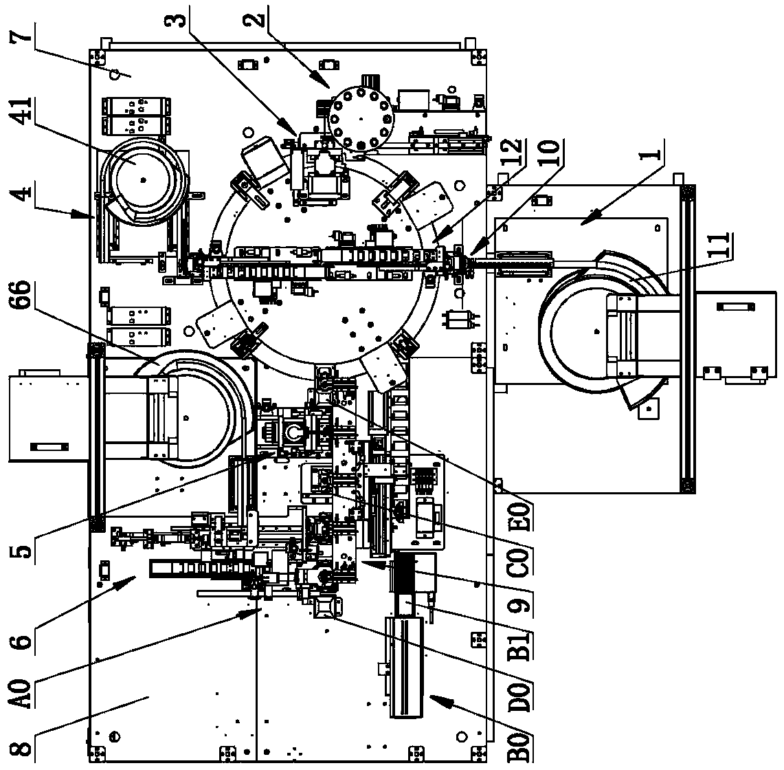
[0039] Such as Figure 1 to Figure 12 As shown, the automatic equipment for assembling parts with magnetic rings includes the conveyor line, and also includes the plastic seat feeding mechanism 1, the magnetic ring feeding mechanism 2, the magnetic ring assembly mechanism 3, the end The plug assembly mechanism 4, the hot-melt mechanism 5 and the lock assembly mechanism 6, the magnetic ring feeding mechanism 2 includes a lower plate 20, an upper plate 21 arranged on the lower plate 20, a first drive for driving the upper plate 20 to rotate Device 22, a plurality of magnetic ring material pipes 23 made of plastic on the upper plate 21, a discharge port 24 communicated with the magnetic ring material pipes 23 on the lower pl...


PUM


Abstract

The invention relates to the technical field of automatic devices, in particular to an automatic device used for assembling a component provided with a magnetic ring. The automatic device comprises aconveying line, a plastic base feeding mechanism, a magnetic ring feeding mechanism, a magnetic ring assembling mechanism, an end plug assembling mechanism, a hot-melting mechanism and a lock catch assembling mechanism, wherein the plastic base feeding mechanism, the magnetic ring feeding mechanism, the magnetic ring assembling mechanism, the end plug assembling mechanism, the hot-melting mechanism and the lock catch assembling mechanism are sequentially arranged on the conveying line in the assembling sequence. The magnetic ring feeding mechanism comprises a lower disc, an upper disc arrangedon the lower disc, a first driving device used for driving the upper disc to rotate, a plurality of magnetic ring tubes arranged on the upper disc and made of plastic, a discharging port formed in the lower disc and communicating with the magnetic ring tubes, a first feeding base arranged at the bottom of the lower disc, a first feeding channel formed in the first feeding base and communicating with the discharging port, a first push rod arranged in the first feeding channel, and a second driving device used for driving the first push rod to push the magnetic ring out of the first feeding channel. By the adoption of the automatic device, automatic assembling and machining of the component provided with the magnetic ring is achieved, and the assembling efficiency is high; and meanwhile, through the design of the magnetic ring feeding mechanism, magnetic rings can be fed one by one.

Description

technical field [0001] The invention relates to the technical field of automation equipment, in particular to an automation equipment for assembling components with magnetic rings. Background technique [0002] Because the magnetic ring is magnetic, the currently commonly used feeding equipment is a vibrating feeding device, but the vibrating plate of the vibrating feeding device is generally made of metal, which will generate suction with the magnetic ring, and the magnetic ring cannot be realized by the vibrating feeding device. Feeding, and when a large number of magnets pour in, the two adjacent magnetic rings will attract each other, but the current feeding device cannot separate the two adjacent magnetic rings, and it is impossible to realize the magnetic rings one by one In addition, at present, when assembling parts with magnetic rings, manual assembly is required, and the assembly efficiency is low. In addition, during the long-term assembly process, work fatigue is...

Claims


Application Information

Patent Timeline
Patent Type & Authority Applications(China)
IPC IPC(8): B23P21/00
CPCB23P21/006
Inventor 黄栋斐
Owner 东莞明控自动化有限公司
Learn More