An automatic turning thread rolling machine

A technology of turning thread rolling machine and thread rolling machine, which is applied to manufacturing tools, other manufacturing equipment/tools, metal processing, etc., can solve the problems of low processing efficiency of metal rods, and achieve the effect of ensuring smooth movement and avoiding jamming

Active Publication Date: 2020-09-08
无锡市伟友汽摩配件有限公司
View PDF6 Cites 0 Cited by
  • Summary
  • Abstract
  • Description
  • Claims
  • Application Information

AI Technical Summary

Problems solved by technology

[0004] The above-mentioned existing technical solutions have the following defects: in actual processing and production, it is usually necessary to turn the metal rod first, and then perform thread rolling on the turned metal rod, and the two production processes of turning and thread rolling are relatively independent. , it is necessary to set up different feeding and unloading devices, and after the turning is completed, it is necessary to ensure that one end of the turned part of the metal rod can be accurately entered into the thread rolling process to be threaded, so that when the metal rod is actually processed, the metal rod Low processing efficiency

Method used


Image

  • An automatic turning thread rolling machine
  • An automatic turning thread rolling machine
  • An automatic turning thread rolling machine

Examples


Embodiment Construction

[0039] The present invention will be described in further detail below in conjunction with the accompanying drawings.

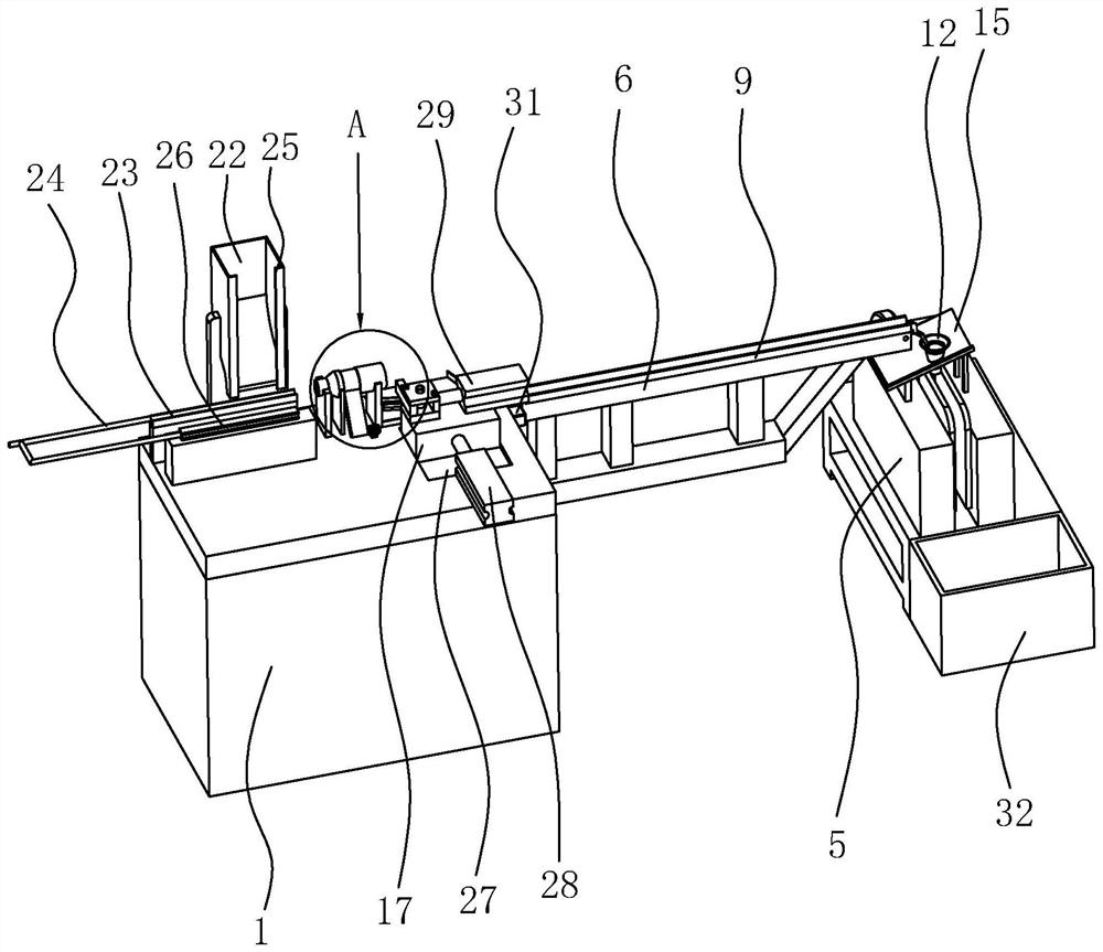
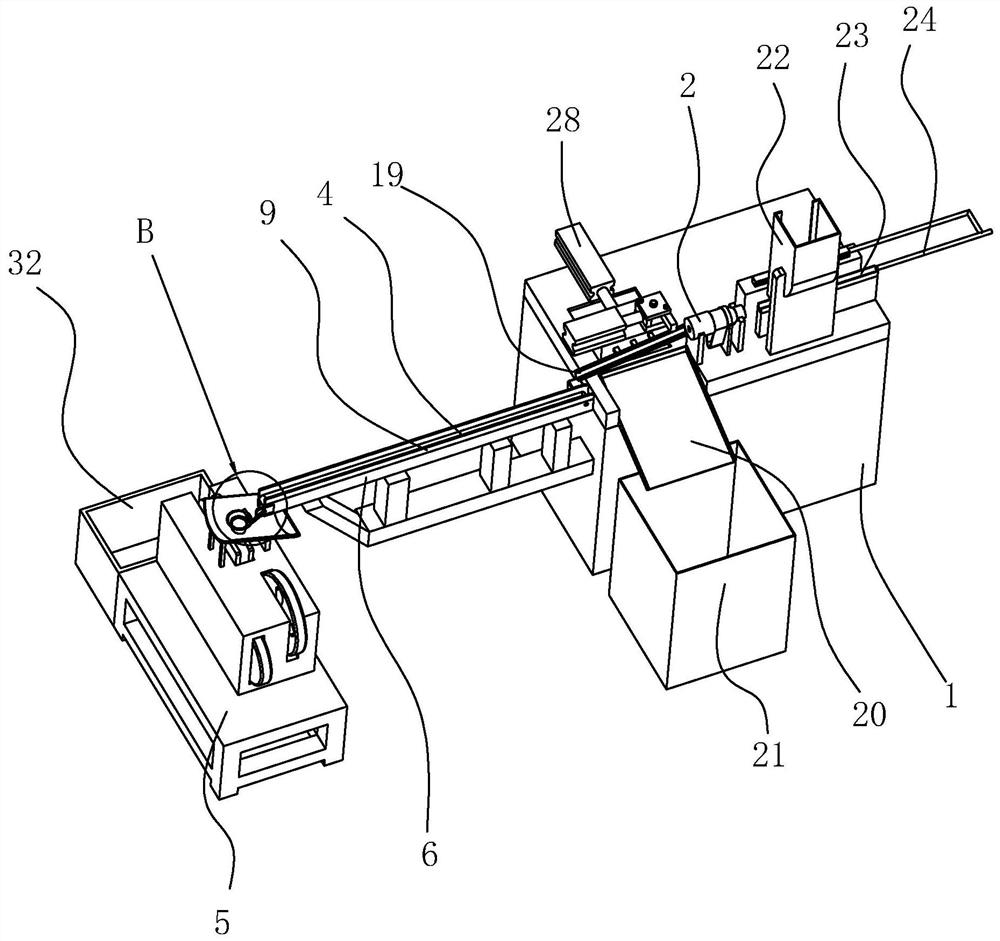
[0040] refer to figure 1 , is a kind of automatic turning thread rolling machine disclosed by the present invention, comprises machine base 1, is provided with feeding device, turning device, conveying transposition device, thread rolling device and unloading device successively on machine base 1; Feeding device comprises The storage rack 22 with openings at the upper and lower ends, the storage rack 22 is cuboid and vertically erected and fixed on the upper end surface of the machine base 1, the thickness of the storage rack 22 is in a trend of decreasing gradually from top to bottom, the storage rack The opening at the lower end of the 22 can only accommodate a metal rod to be processed. The machine base 1 is provided with a slide rail 23 with a U-shaped cross section just below the opening at the lower end of the storage rack 22. The slide rail 23 is arran...


PUM


Abstract

The invention discloses an automatic turning and thread rolling machine, and relates to the technical field of thread machining equipment for metal rods. The automatic turning and thread rolling machine comprises a seat, wherein a loading device, a turning device, a conveying conversion device, a thread rolling device and an unloading device are sequentially arranged on the seat; the turning device comprises a hollow rotary shaft rotationally arranged on the seat, a fixing mechanism used for carrying out rotary fixing on a metal rod which penetrates into the hollow rotary shaft is arranged onthe seat, and a turning tool is slidably arranged on the seat; the conveying conversion device comprises a conveying belt with one end which is located below the turning tool, and a conversion mechanism used for converting the metal rod in a horizontal state to a vertical state is arranged on the seat and at one end away from the turning tool, of the conveying belt; and the thread rolling device comprises a thread rolling machine body, and a discharge end of the conversion mechanism is aligned with a loading end of the thread rolling machine body. According to the automatic turning and threadrolling machine, the turned metal rod is conveyed to the conversion mechanism through the conveying belt and converted, and then subjected to thread rolling by the thread rolling machine body, so thatthe working efficiency of turning and thread rolling for the metal rod is increased.

Description

technical field [0001] The invention relates to the technical field of metal rod thread processing equipment, in particular to an automatic turning thread rolling machine. Background technique [0002] When processing the rearview mirror support rod, it is usually necessary to process a thread at one end of the support rod, and usually the maximum diameter of the helical part on the support rod is smaller than the maximum diameter of the smooth part, which requires turning the metal rod first, and then Thread the turning part, and the thread processing equipment usually has two types: thread rolling machine and thread rolling machine. Compared with thread rolling machine, thread rolling machine is more suitable for such short and small workpieces. It has high processing efficiency and is suitable for high-speed Continuous production. [0003] Patent announcement number is the Chinese patent of CN201147814, has proposed a kind of thread-rolling machine special for spiral hob...

Claims


Application Information

Patent Timeline
Patent Type & Authority Patents(China)
IPC IPC(8): B23P23/04B23Q7/03B23Q7/08
CPCB23P23/04B23Q7/03B23Q7/08
Inventor 朱一帆章翔邱一梦章慧
Owner 无锡市伟友汽摩配件有限公司
Why Eureka
Try Eureka