Tooling fixture for processing steering knuckle

A tooling fixture and steering knuckle technology, which is applied in the direction of manufacturing tools, metal processing equipment, metal processing machinery parts, etc., can solve the problems of low production efficiency, position error, difficult drilling process of steering knuckles, etc., to achieve processing operations, The effect of improving processing efficiency and simplifying the process

Pending Publication Date: 2019-12-20
杭州卫东数控机电有限公司
View PDF0 Cites 0 Cited by
  • Summary
  • Abstract
  • Description
  • Claims
  • Application Information

AI Technical Summary

Problems solved by technology

Since the parts that need to be drilled on the steering knuckle are located on different planes, it is difficult for the steering knuckle to complete the drilling process through the drilling equipment at one time
It is necessary to frequently adjust the clamping position of the steering knuckle, so as to meet the needs of drilling operations for each part. In this way, the production quality of the steering knuckle is greatly improved, and the defective rate is reduced, but the production efficiency is very low. The clamping is still prone to position errors, affecting the accuracy and quality of steering knuckle drilling

Method used


Image

  • Tooling fixture for processing steering knuckle
  • Tooling fixture for processing steering knuckle
  • Tooling fixture for processing steering knuckle

Examples


Embodiment Construction

[0024] It should be noted that, in the case of no conflict, the embodiments of the present invention and the features in the embodiments can be combined with each other.

[0025] In describing the present invention, it should be understood that the terms "center", "longitudinal", "transverse", "upper", "lower", "front", "rear", "left", "right", " The orientations or positional relationships indicated by "vertical", "horizontal", "top", "bottom", "inner" and "outer" are based on the orientations or positional relationships shown in the drawings, and are only for the convenience of describing the present invention and Simplified descriptions, rather than indicating or implying that the device or element referred to must have a particular orientation, be constructed and operate in a particular orientation, and thus should not be construed as limiting the invention. In addition, the terms "first", "second", etc. are used for descriptive purposes only, and should not be understood ...


PUM


Abstract

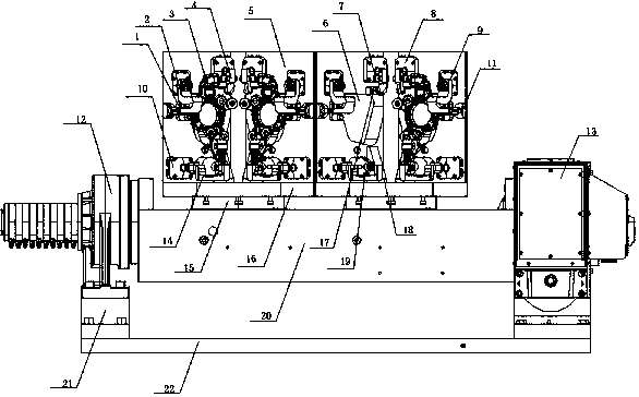
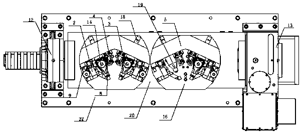
The invention discloses a tooling fixture for machining a steering knuckle. The tooling fixture for machining the steering knuckle comprises a station bottom plate, a machining vertical plate and twogroups of clamping mechanisms, wherein the machining vertical plate is fixed on the station bottom plate, the machining vertical plate is of a V-shaped structure, the two groups of clamping mechanismsare symmetrically arranged on the inner sides of the machining vertical plate respectively, and the clamping mechanisms comprise first pressing oil cylinders, second pressing oil cylinders and thirdpressing oil cylinders; and the power output end of each first pressing oil cylinder is connected with one end of a second pressing block, the power output end of each second pressing oil cylinder isconnected with one end of a first pressing block, and the power output end of each third pressing oil cylinder is connected with one end of a third pressing block. By adopting the technical scheme, the steering knuckle to be machined is clamped through the V-shaped machining vertical plate, two steering knuckle workpieces can be machined simultaneously on the machining vertical plate, and the machining efficiency is greatly improved; the three-point positioning is carried out through every three pressing oil cylinders, so that the clamping of the steering knuckle workpieces is firmer and morestable, and the machining precision is better.

Description

technical field [0001] The invention relates to the technical field of auto parts processing, in particular to a tooling fixture for steering knuckle processing. Background technique [0002] Steering knuckle, also known as "claw horn", is one of the important parts in the steering axle of a car, which can make the car run stably and transmit the driving direction sensitively; the function of the steering knuckle is to transmit and bear the front load of the car, support and drive the front wheel The pin rotates to turn the car; when the car is running, it bears variable impact loads, so it is required to have high strength. [0003] During the production of the steering knuckle, a large number of parts need to be drilled to form bearing holes, and the parts that need to be drilled are set at different positions of the steering knuckle and distributed on different planes. Therefore, the traditional steering knuckle drilling process is usually through manual clamping, and th...

Claims


Application Information

Patent Timeline
Patent Type & Authority Applications(China)
IPC IPC(8): B23Q3/08
CPCB23Q3/082
Inventor 高安锋吴广磊毛伟
Owner 杭州卫东数控机电有限公司
Why Eureka
Try Eureka