Intelligent water supply system under train

An intelligent water supply and train technology, applied in locomotives and other directions, can solve the problems of complicated pipeline structure and control circuit, inconvenient maintenance and cleaning, and poor quality of water pumps, so as to reduce the probability of failure, reduce labor intensity, and ensure passengers. effect of water

Pending Publication Date: 2019-12-20
GEMAC ENG MACHINERY +1
View PDF0 Cites 3 Cited by
  • Summary
  • Abstract
  • Description
  • Claims
  • Application Information

AI Technical Summary

Problems solved by technology

[0003] 1) It affects the space on the car. The water tank is installed on the upper part of both ends of the car, which will inevitably sacrifice the space of other necessary facilities on the roof, resulting in a cramped space
2) The center of gravity of the whole car is high, and each water tank is filled with at least one ton of water. The center of gravity of the whole train is raised, top-heavy, and high-speed driving affects driving safety.
4) Maintenance and cleaning are inconvenient. The water tank is located on the roof interlayer, and maintenance personnel must work in a small space. If the water tank leaks, it will affect the safety of other facilities in the car
[0004] In addition, the water supply method of the existing water tank under the passenger train is generally a single water pump to automatically draw water, the water pump is frequently started, and the quality of the water pump is not good enough, and frequent failures occur, which affects the use
Some use dual water pumps for water supply, the pipeline structure and control circuit of dual water pumps are complex, and the maintenance cost is high

Method used


Image

  • Intelligent water supply system under train
  • Intelligent water supply system under train
  • Intelligent water supply system under train

Examples


Embodiment Construction

[0026] The present invention will be further described below in conjunction with the accompanying drawings.

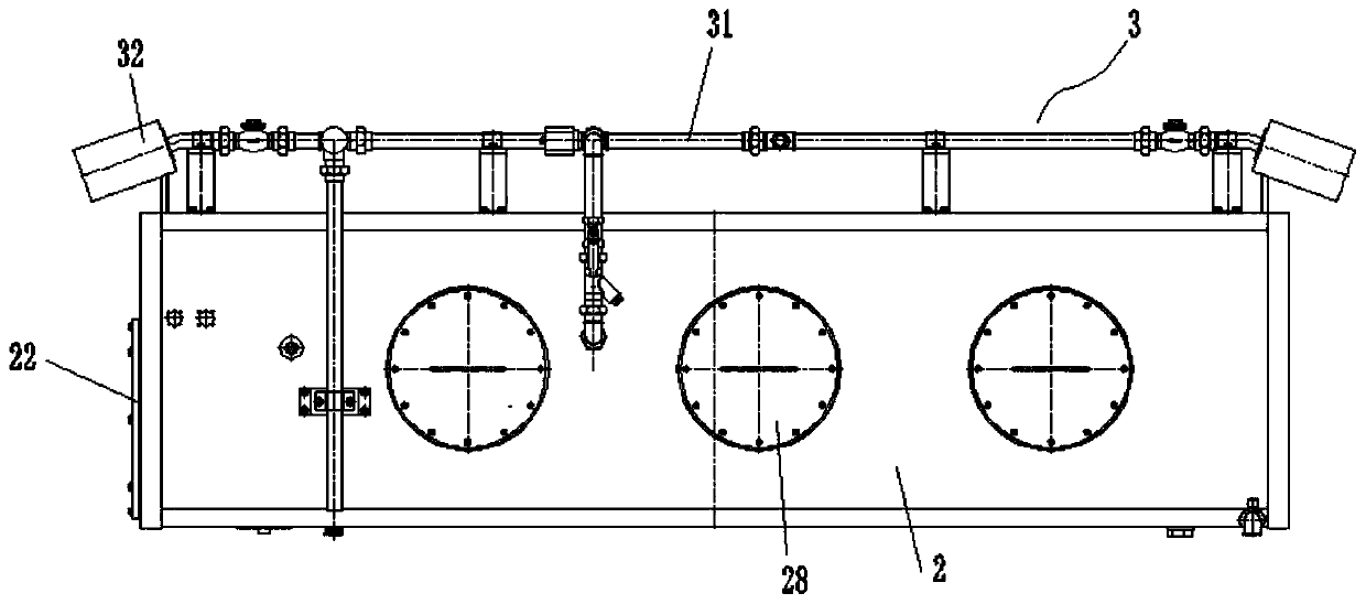
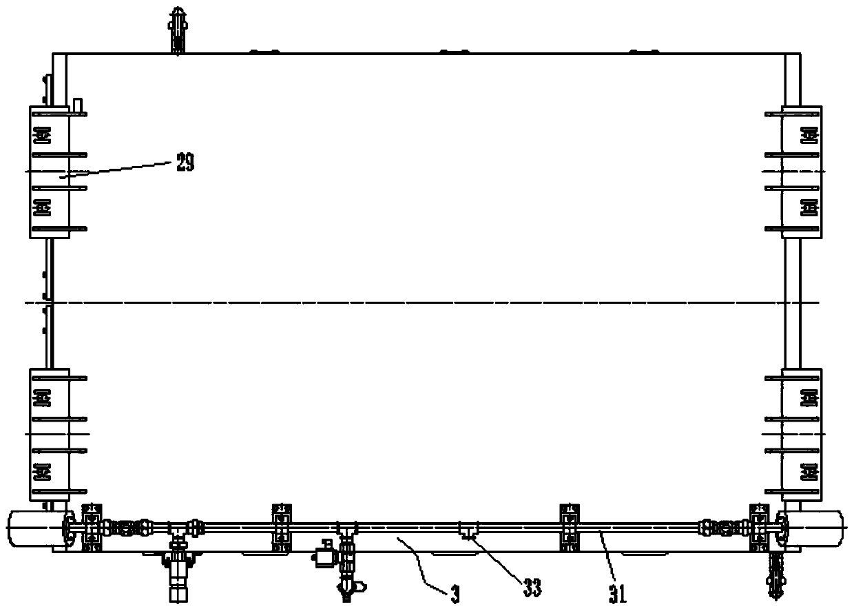
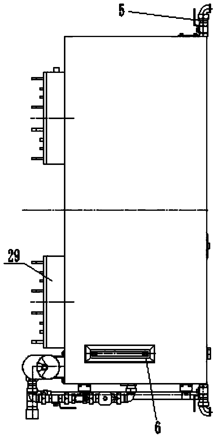
[0027] Such as Figure 1 to Figure 8 , an intelligent water supply system under a train in the present invention, comprising a box body 2, a water injection pipeline 3, an automatic constant pressure water supply unit 4, heating cables and electric heating pipes, the box body 2 is fixed on the bottom of the train body, and an automatic constant pressure water supply unit 4 The water supply unit 4 and the water injection pipeline 3 are both connected to the box body 2, the heating cable is wound on the water injection pipeline 3 and heats the water injection pipeline 3, and the electric heating tube is arranged in the inner cavity of the box body 2 and warms the box body 2 to heat the water in it.

[0028] Such as Figure 6 to Figure 8 , the automatic constant pressure water supply unit 4 in the present invention comprises a pressurized pump 41, an air pressure tank 4...


PUM


Abstract

The invention discloses an intelligent water supply system under a train. A box body is fixed at the bottom of a vehicle body of the train, an automatic constant-pressure water supply unit and a waterinjection pipeline are connected to the box body, a heat tracing belt is wound around the water injection pipeline and heats the water injection pipeline, and an electric heating pipe is arranged inan inner cavity of the box body, and is used for heating water in the box body. The system is arranged at the bottom of the vehicle body of the train, and does not occupy additional space on the vehicle, so that reasonable layout on the vehicle is facilitated, the center of gravity of the whole vehicle is lowered, and high-speed operation of the train is facilitated. According to the system, by utilizing an air pressure tank for the energy storage, frequent starting of a pressurizing pump is avoided, the probability of fault occurrence is reduced, and the service life of a water pump is prolonged; the structure is simple and easy to use, the air pressure tank is connected on a water pipeline in parallel, so that installing is convenient, and the difficulty of an electric appliance controlpart is not increased; and a water tank and the pipeline have cold-proof heating functions, so that the normal use of the water tank under the extremely cold condition in winter is ensured, and wateruse by passengers is guaranteed not to be limited by weather conditions.

Description

technical field [0001] The invention relates to an intelligent water supply system under a train. Background technique [0002] The water supply mode on the existing passenger train is the natural pressure type on the train. Its disadvantages are as follows: [0003] 1) It affects the space on the car. The water tank is installed on the upper part of both ends of the car, which will inevitably sacrifice the space of other necessary facilities on the roof, resulting in a cramped space. 2) The center of gravity of the whole car is high, and each water tank is filled with at least one ton of water. The center of gravity of the whole train is raised, making it top-heavy, and high-speed driving affects driving safety. 3) The volume of the water tank is small. In order to avoid the high center of gravity of the vehicle and ensure driving safety, the volume of the water tank must be reduced to reduce the weight of the water. 4) Maintenance and cleaning are inconvenient. The wate...

Claims


Application Information

Patent Timeline
Patent Type & Authority Applications(China)
IPC IPC(8): B61C17/02
CPCB61C17/02
Inventor 吴振记朱小军冷吉文
Owner GEMAC ENG MACHINERY
Why Eureka
Try Eureka