Bearing vehicle chassis trolley
A technology for carrying vehicles and chassis, applied in the field of carrying vehicles, can solve the problems of large steering torque, difficulty of AGV car as a target vehicle carrying platform, and low precision.
- Summary
- Abstract
- Description
- Claims
- Application Information
AI Technical Summary
Problems solved by technology
Method used
Image
Examples
Embodiment 1
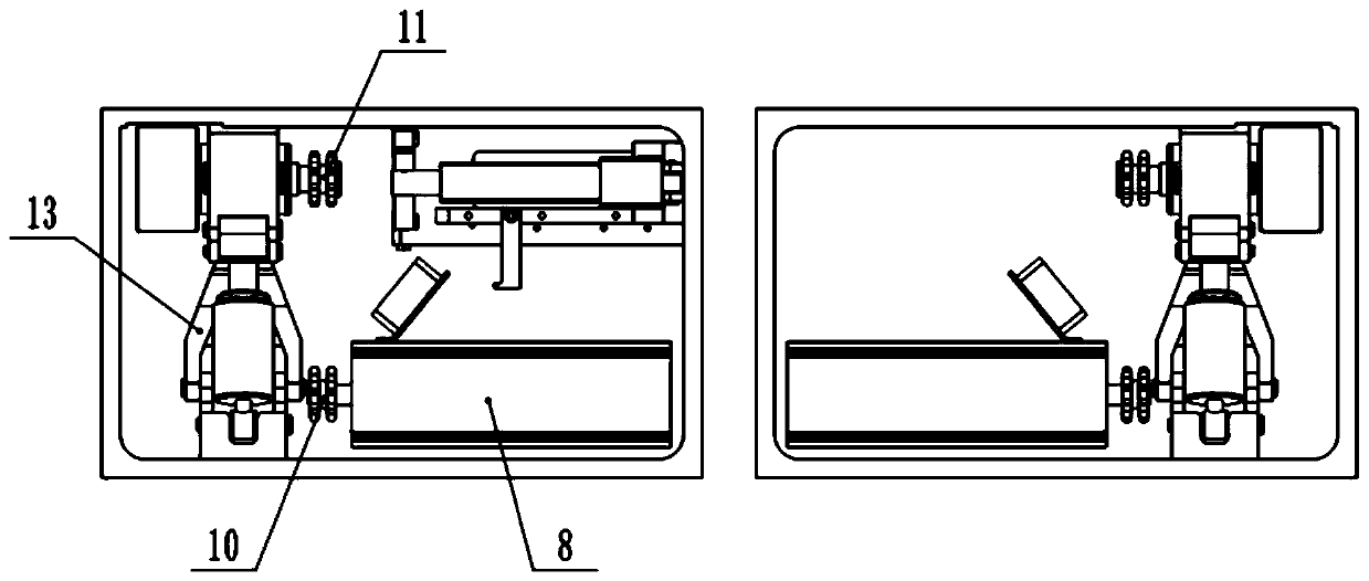
[0041] A chassis trolley of a carrying vehicle comprises a chassis, a driving mechanism, a steering mechanism, a left steering wheel set, a right steering wheel set and a driving wheel set. In this embodiment, the steering mechanism, the left steering wheel set and the right steering wheel set are arranged at the front of the chassis, and the driving mechanism and the driving wheel set are arranged at the rear of the chassis.
[0042] Such as figure 1 and figure 2 As shown, the left steering wheel set includes the left steering wheel 9, the left turning lever 1 and the left fixed piece 7; the right steering wheel set includes the right steering wheel, the right turning lever and the right fixing piece; the left steering wheel 9 and the right steering wheel They are respectively arranged on the left and right sides of the front part of the chassis.
[0043] Specifically, take the left steering wheel 9 as an example, the left fixed piece 7 is a triangle, the left turning rod ...
Embodiment 2
[0057] A trolley with a chassis of a carrying vehicle is different from Embodiment 1 in that it further includes two brake mechanisms. Both the left steering wheel set and the right steering wheel set correspond to a braking mechanism. The left turning rod 1 rear end is provided with a rotating shaft hole along the axis of the left steering wheel 9.
[0058] Such as Figure 5 As shown, taking the brake mechanism corresponding to the left steering wheel set as an example, the brake mechanism includes a hydraulic caliper 14, a brake pad 15, a brake shaft 16, a telescopic rod 17, two universal joints and a front shaft 18. Front rotating shaft 18 passes through the rotating shaft hole, and one end of front rotating shaft 18 is welded with left steering wheel 9, and the other end of front rotating shaft 18 is connected with an end of telescopic rod 17 by a universal joint, and the other end of telescopic rod 17 passes through another universal joint. Joint is connected with one e...
Embodiment 3
[0062] A chassis trolley of a carrier vehicle, the difference from Embodiment 1 is that the push rod adopts a hydraulic push rod.
[0063] It also includes a detection mechanism, which includes a temperature sensor, a hydraulic sensor, a processing unit and an alarm unit; the temperature sensor is bonded to the casing of the hydraulic push rod to detect the temperature at the shell of the shock absorber; the hydraulic sensor is bonded to the hydraulic push rod The inside of the rod, used to detect the hydraulic pressure inside.
[0064] The processing unit is signal-connected with the temperature sensor and the hydraulic pressure sensor, and the processing unit is used for receiving the temperature signal of the temperature sensor and the hydraulic pressure signal of the hydraulic pressure sensor. The temperature threshold and the hydraulic threshold are pre-stored in the processing unit; the processing unit is used to compare the temperature signal with the temperature thresh...
PUM
 Abstract
Description
Claims
Application Information
 - R&D
- Intellectual Property
- Life Sciences
- Materials
- Tech Scout
- Unparalleled Data Quality
- Higher Quality Content
- 60% Fewer Hallucinations
Browse by: Latest US Patents, China's latest patents, Technical Efficacy Thesaurus, Application Domain, Technology Topic, Popular Technical Reports.
© 2025 PatSnap. All rights reserved.Legal|Privacy policy|Modern Slavery Act Transparency Statement|Sitemap|About US| Contact US: help@patsnap.com


