Cloth winding drum split winding mechanism

A cloth reel and rack technology, applied in the direction of winding strips, thin material handling, transportation and packaging, etc., can solve the problems of troublesome installation and disassembly, long replacement time, long downtime, etc., to achieve convenient installation and disassembly, automation High degree of effect with less downtime

Active Publication Date: 2019-12-20
台州精微顺自动化有限公司
View PDF9 Cites 3 Cited by
  • Summary
  • Abstract
  • Description
  • Claims
  • Application Information

AI Technical Summary

Problems solved by technology

[0002] When the cloth is being processed, it needs to separate the entire roll of cloth into multiple sub-rolls. However, the existing cloth winding and unwinding mechanism has a complex structure and troublesome installation. Generally, the entire roll of cloth needs to be installed On the fabric reel roller, fix the two ends of the fabric reel roller on the two reel seats or unwinding seats. It is troublesome to install and disassemble. It is necessary to open the upper cover of the reel seat and then install it. Then the upper cover is fixed by bolts, which is very troublesome, and the replacement time in the middle is long, and the downtime is long

Method used


Image

  • Cloth winding drum split winding mechanism
  • Cloth winding drum split winding mechanism
  • Cloth winding drum split winding mechanism

Examples


Embodiment Construction

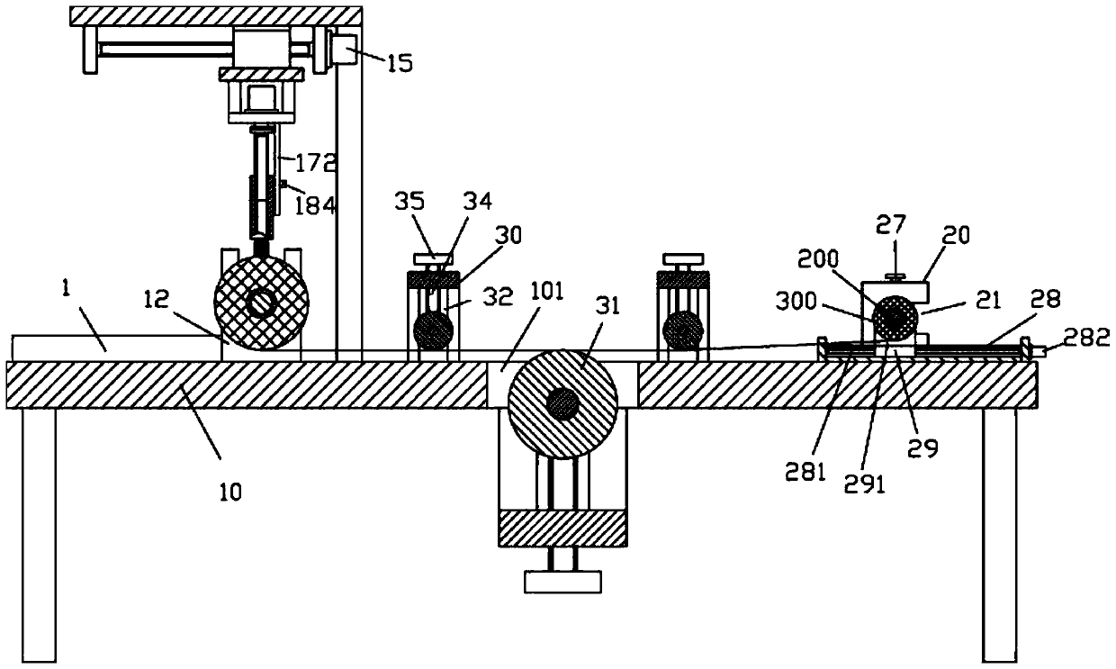
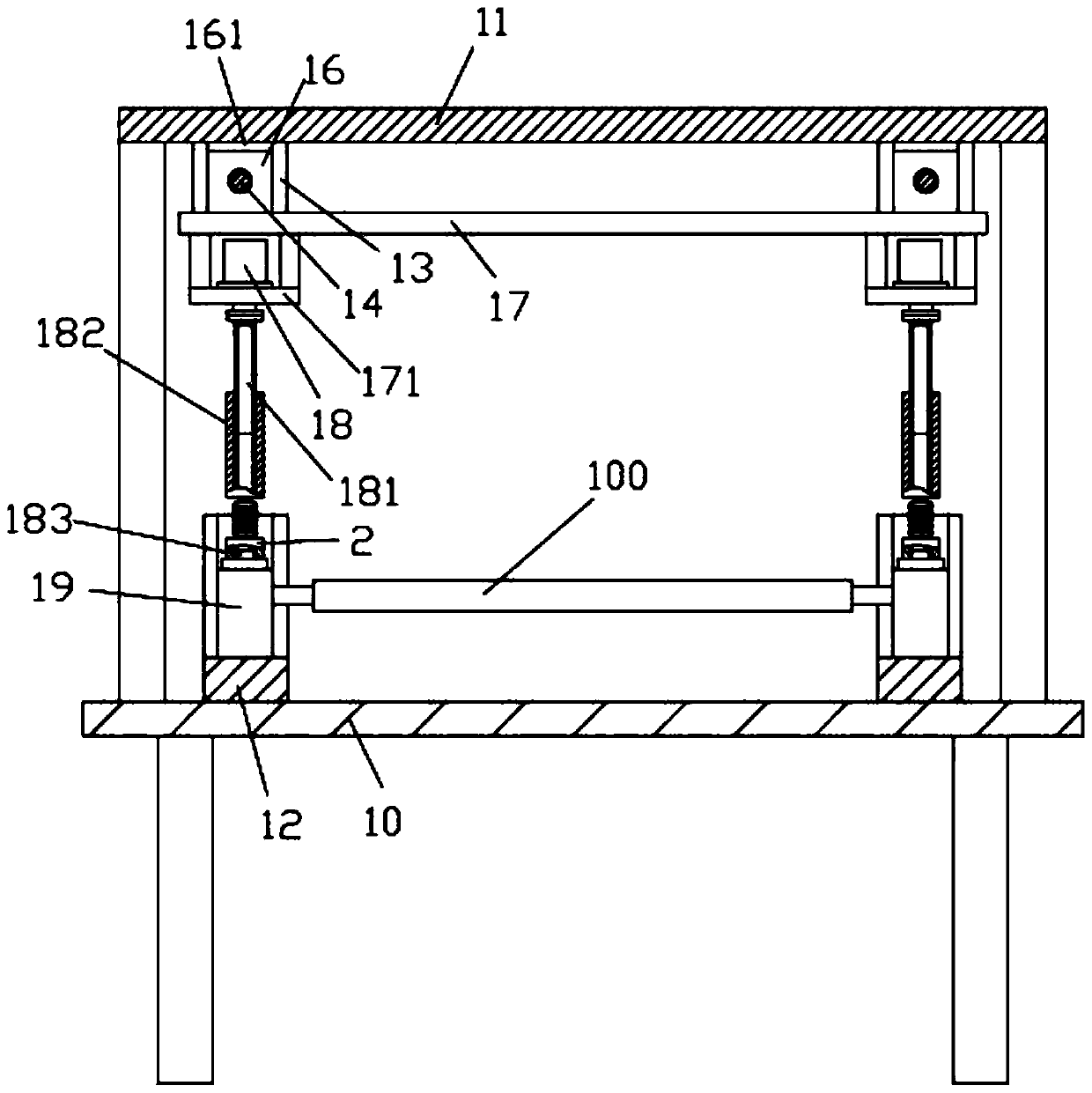
[0025] Examples, see e.g. figure 1 and Figure 6 Shown, a kind of cloth reel sub-rolling mechanism comprises frame 10, and the front end top surface of the top plate of described frame 10 is fixed with support frame 11 and two placement frames 12, and the rear end top surface of the top plate of frame 10 The left and right parts of the winding support block 20 are fixed, and a winding roller 200 is arranged between the two winding support blocks 20;

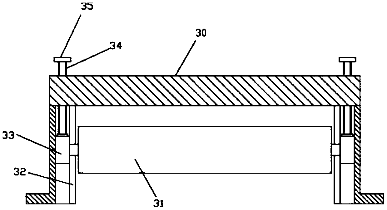
[0026] The middle part of the top plate of the frame 10 has a main middle part through groove 101, and the middle part of the bottom surface of the top plate of the frame 10 is fixed with an adjusting frame 30, and the top plate of the frame 10 at the front part and the rear part of the main middle part through groove 101 An adjustment frame 30 is fixed on the top surface, and the adjustment frame 30 is provided with an adjustment tension roller 31, and the top of the adjustment tension roller 31 of the adjustment frame 30 below...


PUM


Abstract

The invention discloses a cloth winding drum split winding mechanism. The mechanism comprises a machine frame, wherein a support frame and two placement frames are fixed to the top surface of the front end of a top plate of the machine frame, winding support blocks are fixed to the left part and the right part of the top surface of the rear end of the top plate of the machine frame, and a windingroller is arranged between the two winding support blocks. According to the cloth winding drum split winding mechanism, the two ends of a cloth winding drum roller can be mounted on a roller body connecting seat, and the roller body connecting seat can be automatically lifted, lowered and conveyed; when the mechanism is disassembled, the roller body connecting seat and the cloth winding drum roller are taken out at the same time, and a new cloth winding drum roller with a new roller body connecting seat well mounted is directly lifted, conveyed and lowered, thus completing the installation, and in this way, automatic mounting and dismounting of the cloth winding drum roller is achieved, high efficiency and fast replacement can be achieved; and meanwhile, a winding structure is simple in structure, and the winding roller and a rotary connecting block can be automatically mounted on the winding support blocks through the operation of a mobile main motor, mounting and dismounting are convenient, the automation degree is high, and the production efficiency is greatly improved.

Description

Technical field: [0001] The invention relates to the technical field of textile equipment, and more specifically relates to a fabric reel splitting mechanism. Background technique: [0002] When the cloth is being processed, it needs to separate the entire roll of cloth into multiple sub-rolls. However, the existing cloth winding and unwinding mechanism has a complex structure and troublesome installation. Generally, the entire roll of cloth needs to be installed On the fabric reel roller, fix the two ends of the fabric reel roller on the two reel seats or unwinding seats. It is troublesome to install and disassemble. It is necessary to open the upper cover of the reel seat and then install it. It is very troublesome to fix the upper cover by bolts, and the replacement time in the middle is long, and the downtime is long. Invention content: [0003] The purpose of the present invention is to overcome the deficiencies of the prior art and provide a fabric reel splitting me...

Claims


Application Information

Patent Timeline
Patent Type & Authority Applications(China)
IPC IPC(8): B65H18/02B65H18/08B65H19/30
CPCB65H18/02B65H18/08B65H19/30B65H2701/19
Inventor 罗更荣
Owner 台州精微顺自动化有限公司
Why Eureka
Try Eureka