Novel spraying-direction gradual-change type mortar throwing-ejection device

A gradient, mortar technology, applied in the direction of architecture, building structure, etc., can solve the problems of high energy consumption, large structure, complex structure, etc., and achieve the effect of uniform spraying of mortar

Pending Publication Date: 2019-12-20
李爱芹
View PDF0 Cites 2 Cited by
  • Summary
  • Abstract
  • Description
  • Claims
  • Application Information

AI Technical Summary

Problems solved by technology

Therefore, its structure is complex, the structure is larger, and the energy consumption is higher

Method used


Image

  • Novel spraying-direction gradual-change type mortar throwing-ejection device
  • Novel spraying-direction gradual-change type mortar throwing-ejection device
  • Novel spraying-direction gradual-change type mortar throwing-ejection device

Examples


Embodiment 1

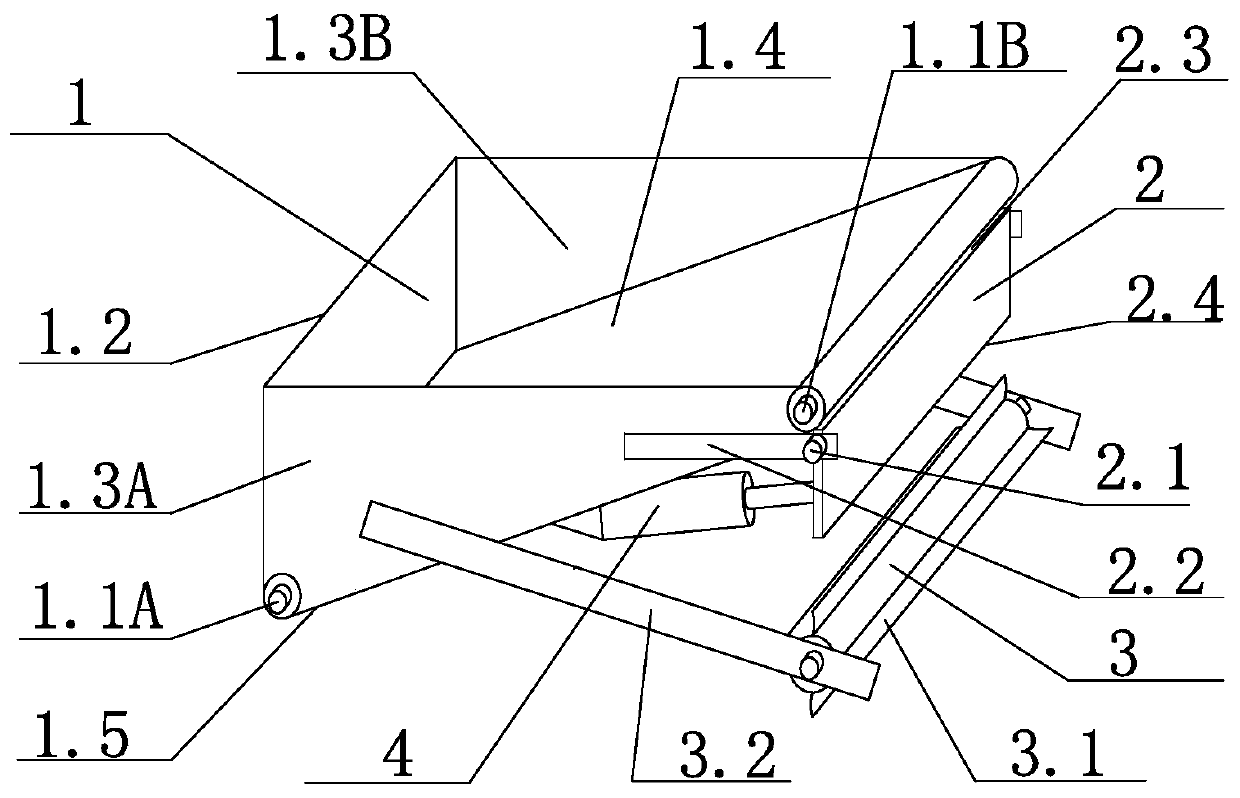
[0047] Such as Figure 1-Figure 4 As shown, the new spraying direction gradual change type mortar ejection device of the present invention comprises a hopper, the bottom of the hopper is provided with a conveyor belt 1.4 which is inclined to transport upwards, a material guide plate 2 is provided below the outlet end of the conveyor belt 1.4, and two tops of the material guide plate 2 are provided. The material guide plate support 2.2 is hinged on the side, the material guide plate support 2.2 is connected to the hopper, the bottom end of the material guide plate 2 is connected to the hopper through a movable joint, and a mortar throwing roller 3 is arranged below the material guide plate 2 . The hopper includes the hopper body 1, the side elevation A1.3A, the side elevation B1.3B, and the end elevation 1.2 constitute the three elevations of the hopper body 1. The inclined bottom surface of the hopper is a conveyor belt, and a bottom shell 1.5 is arranged below the conveyor bel...

Embodiment 2

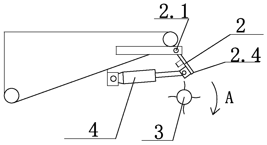
[0064] The movable range of the material guide plate 2 is located, and the material guide plate 2 is vertically arranged downwards, corresponding to the inner side of the cylinder horizontal diameter of the mortar throwing roller 3; and corresponding to the horizontal diameter of the mortar throwing roller 3 in the vertical direction with the bottom end of the material guide plate 2 between the outer ends. Such as figure 2 As shown, the material guide plate is at the far right; Figure 4 As shown, the material guide plate is at the leftmost state; when the electric push rod pushes the material guide plate to move, it moves between the leftmost end and the rightmost end. All the other are with embodiment 1.

Embodiment 3

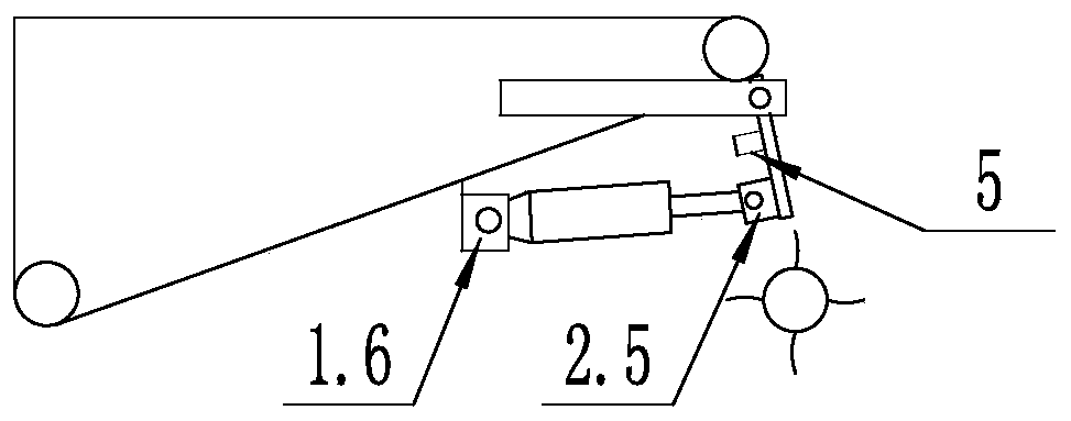
[0066] Such as Figure 5-Figure 6 As shown, the edge 2.3 on the material guide plate is in the shape of a knife edge. Such as Figure 6 As shown, the material guide plate is in the shape of a knife on one side. All the other are with embodiment 2.


PUM


Abstract

The invention relates to a novel spraying-direction gradual-change type mortar throwing-ejection device, and belongs to the field of mortar spraying machine manufacturing in the field of architecturaldecoration machine manufacturing. The mortar throwing-ejection device comprises a hopper, wherein the bottom of the hopper is provided with a conveyor belt conveying in a way of inclining upward, a guide plate is arranged below the outlet end of the conveyor belt, a guide plate support is hinged to two sides of the top end of the guide plate, the guide plate support is connected with the hopper,the bottom end of the guide plate is connected with the hopper by a movable connecting piece, and a mortar throwing-ejection roller is arranged below the guide plate. The spraying-direction gradual-change type mortar throwing-ejection device can realize progressive changes in three spraying directions of downward ahead, dead ahead and upward ahead, and mortar throw-ejected by the device is more uniform.

Description

technical field [0001] The invention relates to a novel spraying direction gradient type mortar jetting device, which belongs to the field of mortar spraying machinery manufacturing in the field of building decoration machinery manufacturing. Background technique [0002] In the prior art, the spraying direction gradient mortar spraying device is driven by the mechanical lifting mechanism, faces the working wall, rises from the bottom of the wall to the top of the wall, and shoots the mortar to the building wall, and the mortar is thrown to the wall. After the building wall is finished, the subsequent mortar troweling operation is carried out to form a gray layer, which is the so-called plastering of the building wall. [0003] Existing spray technology defects are as follows: [0004] The mortar throwing drum performs both rotary motion and circular motion, and performs two motions at the same time. The direction of the resultant force of the two movements is constantly c...

Claims


Application Information

Patent Timeline
Patent Type & Authority Applications(China)
IPC IPC(8): E04F21/08
CPCE04F21/08
Inventor 张兴波张培妍陈政达徐鑫炜吴昌润
Owner 李爱芹
Why Eureka
Try Eureka