Tunnel routing inspection method

A technology in tunnels and tunnels, applied in the fields of earth-moving drilling, television, mining equipment, etc., can solve the problems of low overall efficiency of tunnel inspection operations, complex structure of large flaw detection vehicles, and low timeliness of flaw detection vehicles, so as to facilitate real-time processing. , Improve the recognition speed and splicing speed, the effect of fast recognition speed

Active Publication Date: 2019-12-20
SHANGHAI ORIENTAL MARITIME ENG TECH CO LTD
View PDF12 Cites 5 Cited by
  • Summary
  • Abstract
  • Description
  • Claims
  • Application Information

AI Technical Summary

Problems solved by technology

[0003] At present, domestic tunnel inspection work mainly relies on manual work, which leads to low overall efficiency, low accuracy, easy missed inspections, and long time-consuming tunnel inspection operations.
At present, the automatic intelligent inspection devices are mostly used in large-scale inspection vehicles with complex structures and high costs. In particular, the existing inspection inspection vehicles are not time-sensitive, and tunnel image collection is required first. Due to the difficulty of image processing and the speed It is slow. After collecting all the images of the tunnel, the tunnel image processing and disease point detection will be performed on the background platform. After the disease is found, it will be notified to the maintenance and other departments to deal with it. This will lead to a very long cycle of tunnel inspection and post-processing.

Method used


Image

  • Tunnel routing inspection method
  • Tunnel routing inspection method
  • Tunnel routing inspection method

Examples


Embodiment Construction

[0036] In order to more clearly illustrate the embodiments of the present invention or the technical solutions in the prior art, the specific implementation manners of the present invention will be described below with reference to the accompanying drawings. Obviously, the accompanying drawings in the following description are only some embodiments of the present invention, and those skilled in the art can obtain other accompanying drawings based on these drawings and obtain other implementations.

[0037] In order to make the drawing concise, each drawing only schematically shows the parts related to the present invention, and they do not represent the actual structure of the product. In addition, to make the drawings concise and easy to understand, in some drawings, only one of the components having the same structure or function is schematically shown, or only one of them is marked. Herein, "a" not only means "only one", but also means "more than one".

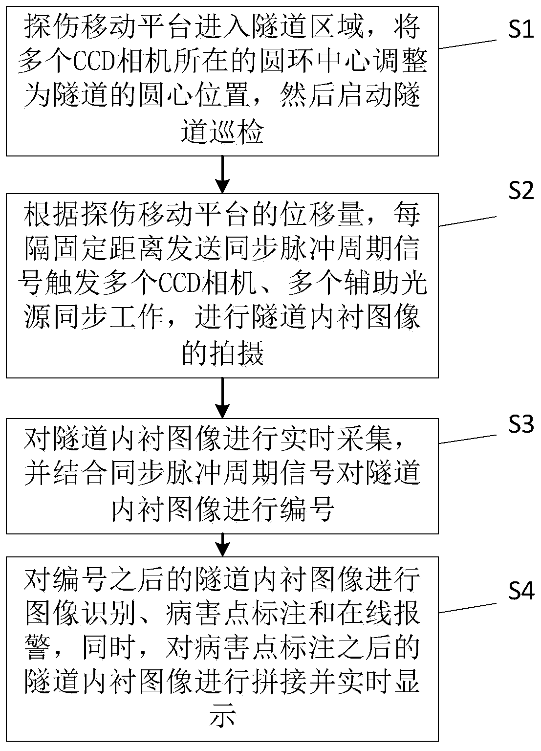
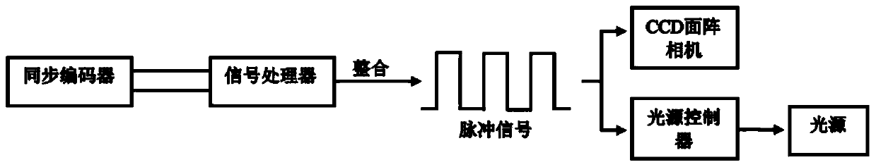
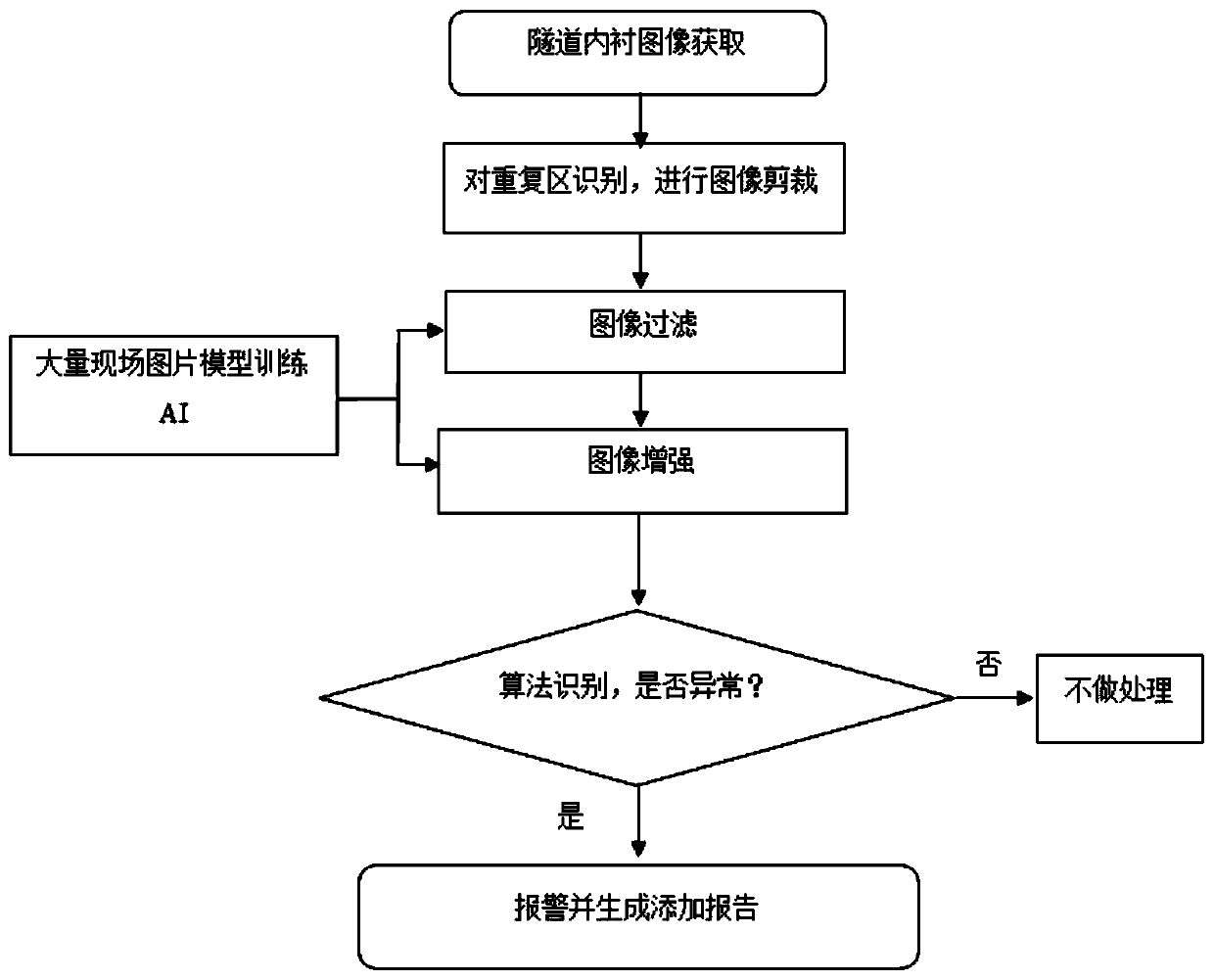
[0038] A tunnel i...


PUM


Abstract

The invention discloses a tunnel routing inspection method. The method includes the following steps that S1, a flaw detection movement platform enters a tunnel area, the center of a circular ring where a plurality of CCD cameras on the flaw detection movement platform are located is adjusted to be the circle center position of a tunnel, thus the distances between the plurality of CCD cameras and atunnel lining surface are consistent, and then tunnel routing inspection is started; S2, according to the displacement amount of the flaw detection movement platform, synchronous pulse periodic signals are sent at intervals of fixed distance so as to trigger the plurality of CCD cameras and a plurality of auxiliary light sources to work synchronously, and tunnel lining images are shot; S3, the tunnel lining images are collected in real time and are numbered in combination with the synchronous pulse periodic signals; and S4, the numbered tunnel lining images are subjected to image recognitionand trouble spot marking, and meanwhile the tunnel lining images which are already subjected to trouble spot marking are spliced and displayed in real time. The tunnel routing inspection method has the technical characteristics that the detection speed is high, the timeliness is high, the recognition accuracy is high, routing inspection positioning is accurate, and the shot images are clear.

Description

technical field [0001] The invention belongs to the technical field of tunnel inspection, and in particular relates to a tunnel inspection method. Background technique [0002] With the rapid development of urban rail transit in recent years, more and more attention has been paid to the safety of subway tunnels; tunnel problems such as cracking, leakage, and cable leakage in the tunnel will seriously affect the safety of rail transit, so tunnel inspection work is appears to be particularly important. [0003] At present, domestic tunnel inspection work mainly relies on manual work, which leads to low overall efficiency, low accuracy, easy missed inspections, and long time-consuming tunnel inspection operations. At present, the automatic intelligent inspection devices are mostly used in large-scale inspection vehicles with complex structures and high costs. In particular, the existing inspection inspection vehicles are not time-sensitive, and tunnel image collection is requi...

Claims


Application Information

Patent Timeline
Patent Type & Authority Applications(China)
IPC IPC(8): E21F17/18H04N7/18
CPCE21F17/18H04N7/181
Inventor 姚继东余天乐盛忠义张建强朱继东陆旭红钱伟翔
Owner SHANGHAI ORIENTAL MARITIME ENG TECH CO LTD
Why Eureka
Try Eureka