Inner ring stop mechanism of wheel hub bearing

A technology of hub bearings and stop mechanisms, which is applied in the direction of hubs, bearing components, shafts and bearings, etc., which can solve the problems of maintenance-free hub bearings that cannot be adjusted, high machining accuracy requirements for hub parts, and difficulty in assembly and maintenance of hub bearings. , to achieve the effect of convenient adjustment of hub bearing clearance, efficient and economical processing, convenient and quick assembly and maintenance

Pending Publication Date: 2019-12-20
彭绍文
View PDF1 Cites 5 Cited by
  • Summary
  • Abstract
  • Description
  • Claims
  • Application Information

AI Technical Summary

Problems solved by technology

[0007] In order to solve the problems of difficulty in assembly and maintenance of wheel hub bearings, runaway inner circle of wheel hub bearings, inability to adjust the clearance of maintenance-free hub bearings, and high processing precision requirements for maintenance-free hub parts, the invention provides a stop mechanism for the inner ring of hub bearings

Method used


Image

  • Inner ring stop mechanism of wheel hub bearing
  • Inner ring stop mechanism of wheel hub bearing
  • Inner ring stop mechanism of wheel hub bearing

Examples


Embodiment Construction

[0033] The technical solution of the present invention will be clearly and completely described below in conjunction with the accompanying drawings, but this embodiment should not be construed as limiting the present invention.

[0034] It should be noted that: the shaft head referred to in this application is also referred to as a half-shaft sleeve or a hub shaft tube, which is defined as a shaft head in the present invention.

[0035] The present invention as Figure 1 to Figure 5 Shown:

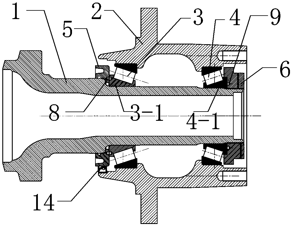
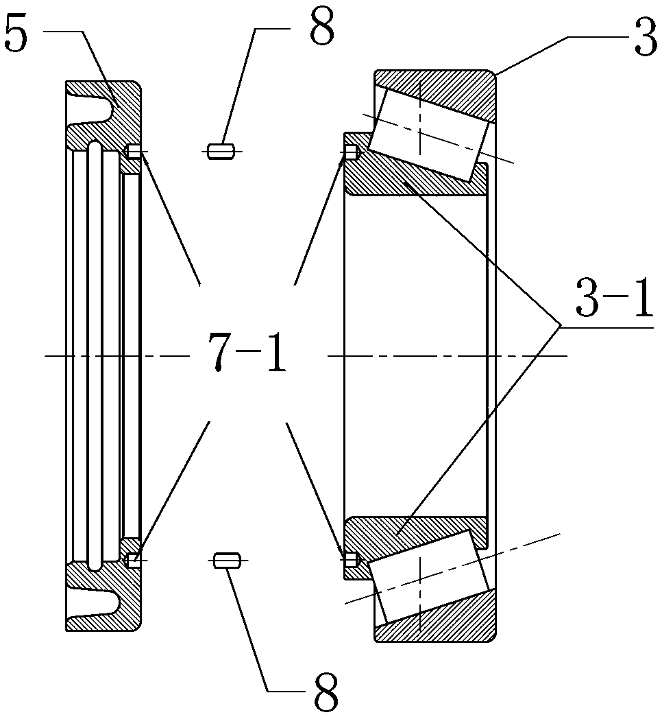
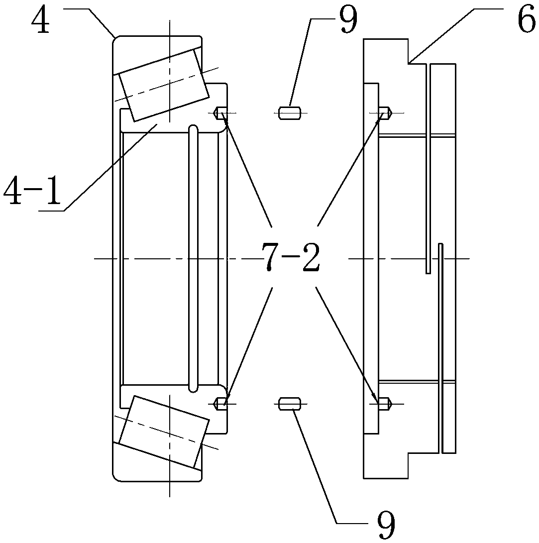
[0036] A stopping mechanism for the inner ring of a wheel hub bearing, comprising a shaft head 1 with a limit step surface, and a wheel hub 2, the wheel hub 2 is set on the shaft head through the wheel hub inner bearing 3 and the wheel hub outer bearing 4 arranged in its inner cavity, wherein: The inner ring 3-1 of the hub inner bearing is limited by abutting against the limit step surface of the shaft head through the bearing race 5, and the bearing race includes a radial contact surface...


PUM


Abstract

The invention discloses an inner ring stop mechanism of a wheel hub bearing. The inner ring stop mechanism includes a shaft head with a limiting stepped surface and a wheel hub with a limiting steppedsurface. The wheel hub sleeves the shaft head through a wheel hub inner bearing and a wheel hub outer bearing arranged in an inner cavity of the wheel hub, and the wheel hub inner bearing is abuttedagainst the limiting stepped surface of the shaft head for limiting through a bearing race. The wheel hub outer bearing is locked and fixed by a locking nut, the bearing race and the shaft head are ininterference fit connection, an inner ring of the wheel hub inner bearing and an inner ring of the wheel hub outer bearing are in clearance fit connection with the shaft head, the inner ring of the wheel hub inner bearing and the bearing race limit the circumferential rotation of the wheel hub inner bearing relative to the shaft head through a circumferential limiting structure between the binding surfaces of the inner ring of the wheel hub inner bearing and the bearing race, and the inner ring of the wheel hub outer bearing and the locking nut limit the circumferential rotation of the wheelhub outer bearing relative to the shaft head through a circumferential limiting structure between the binding surfaces of the inner ring of the wheel hub outer bearing and the locking nut. The problems that the wheel hub bearings are difficulty in assembling and maintaining, the inner rings of the hub bearings are in clearance fit, clearance of the maintenance-free wheel hub bearings are unable tobe adjusted, and the requirement of the machining precision of parts is high are solved.

Description

technical field [0001] The invention relates to the technical field of automobile structures, in particular to a stop mechanism for an inner ring of a hub bearing. Background technique [0002] At present, the hub bearings of the rear axle wheel ends of commercial vehicles in the market generally adopt the following two methods: [0003] wheel end form Cooperating method between hub inner bearing inner ring and shaft head Hub inner bearing inner ring and shaft head stop method Cooperating method between hub outer bearing inner ring and shaft head Hub Outer Bearing Inner Ring and Shaft Head Stopping Method common wheel end interference fit Radial interference fit holding force over fit End friction maintenance-free wheel ends clearance fit End friction clearance fit End friction [0004] In the process of realizing the present invention, the inventor found that the existing two stop methods have at least the following disadvantag...

Claims


Application Information

Patent Timeline
Patent Type & Authority Applications(China)
IPC IPC(8): F16C35/063F16C35/067B60B27/00
CPCB60B27/0084F16C35/063F16C35/067
Inventor 彭绍文
Owner 彭绍文
Why Eureka
Try Eureka