Overload protection gear for intelligent lock

An overload protection and lock technology, which is applied in the field of locks, can solve problems such as insufficient lock sealing, poor lock stability, and increased load, and achieve the effects of enhancing stability and reliability, prolonging service life, and avoiding maintenance and replacement

Pending Publication Date: 2019-12-20
广东好太太智能家居有限公司
View PDF8 Cites 1 Cited by
  • Summary
  • Abstract
  • Description
  • Claims
  • Application Information

AI Technical Summary

Problems solved by technology

[0003] In the daily use of smart locks, sometimes the load of the lock is greater than expected: for example, there is a processing error in the lock groove on the door frame that matches the lock tongue, and the groove is made shallow, causing the lock tongue to be pushed to death before it is in place. However, the motor continues to drive, causing the load inside the lock to suddenly increase, causing damage to the transmission gear or the reduction box; or the lock is not sealed enough, foreign matter enters the interior, and the lubrication performance is insufficient, which will cause the gear to freeze or If the lock is stuck, the load will suddenly increase; even some curious and playful children artificially stop the movement of the lock tongue during the working process of the lock, forcefully pull or tighten the lock tongue, and the motor continues to drive at the same time, which will also cause Damage to gears or reduction housings
[0004] In this way, the stability of the lock is relatively poor, there is no better overload protection method, and it cannot withstand various emergencies in daily life, resulting in the lock being easily damaged, and the frequency of maintenance and replacement is high, which brings great inconvenience to consumers. bad user experience

Method used


Image

  • Overload protection gear for intelligent lock
  • Overload protection gear for intelligent lock
  • Overload protection gear for intelligent lock

Examples


Embodiment Construction

[0019] Below, the present invention will be further described in conjunction with the accompanying drawings and specific implementation methods. It should be noted that, under the premise of not conflicting, the various embodiments described below or the technical features can be combined arbitrarily to form new embodiments. .

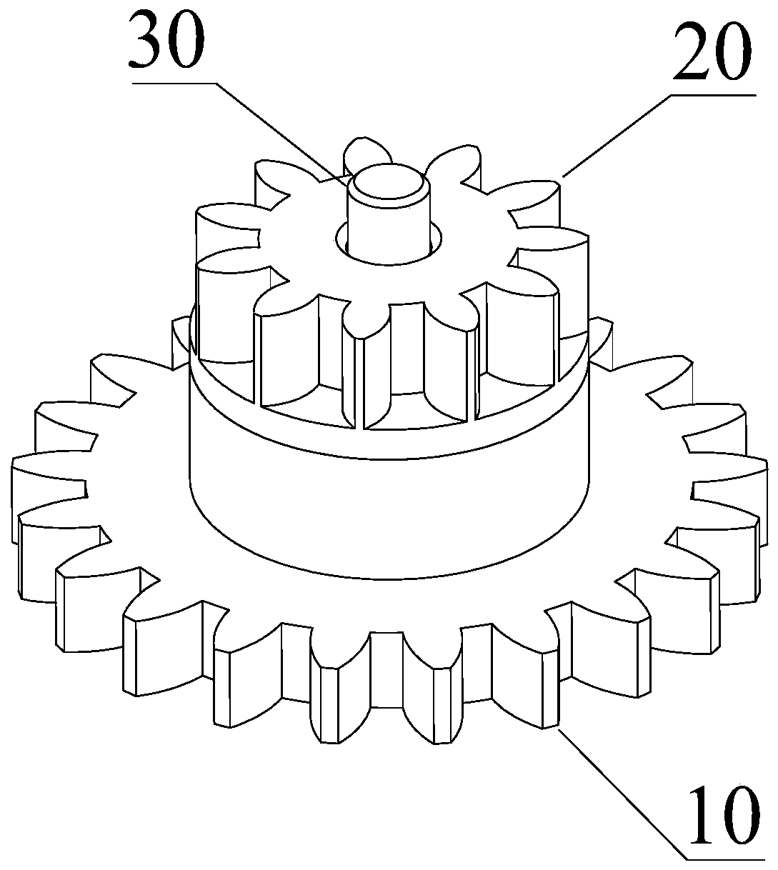
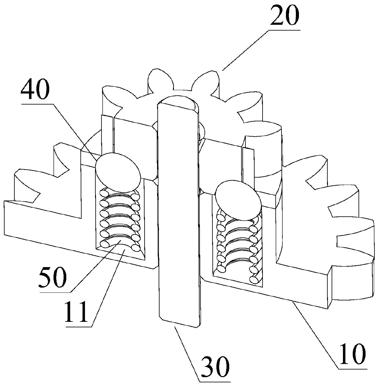
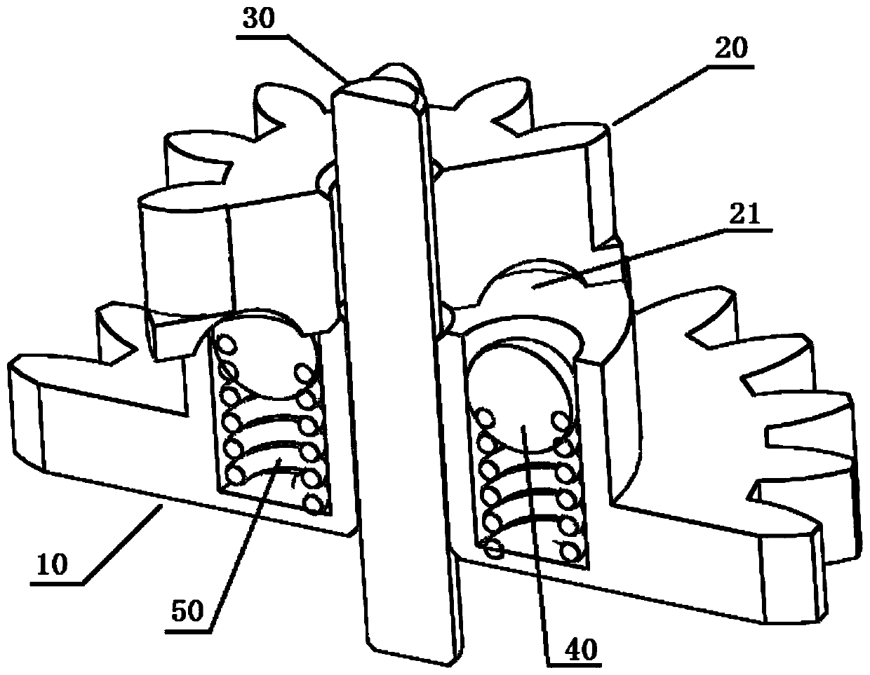
[0020] refer to Figure 1-Figure 4 , the present invention discloses an overload protection gear for transmission inside an intelligent lock, including: an input gear 10, an output gear 20, a gear shaft 30, a spherical body and an elastic body. The output gear 20 is connected to the reduction box of the smart lock, and the output gear 20 is connected to the deadbolt of the smart lock, so as to transmit the torque output by the motor and the reducer to the deadbolt, so that the deadbolt can perform telescopic movement to realize unlocking and locking. function of the lock.

[0021] Wherein, both the input gear 10 and the output gear 20 are pivotally c...


PUM


Abstract

The invention discloses an overload protection gear for an intelligent lock. The overload protection gear comprises an input gear, an output gear, a gear shaft, a round ball body and an elastic piece,wherein the input gear and a speed reducer case of the intelligent lock are in transmission connection, the output gear and a spring bolt of the intelligent lock are in transmission connection, the input gear and the output gear are both pivoted on the gear shaft, the output gear and the input gear are both axially fixed, the output gear abuts against the top of the input gear, the input gear isinternally provided with a spring groove for accommodating the elastic piece, the elastic piece is arranged in the spring groove, the round ball body is arranged at the top of the elastic piece, a spherical pit is formed in the bottom of the output gear, the upper part of the round ball body is accommodated in the spherical pit, and the lower part of the round ball body is accommodated in the spring groove and compress the elastic piece. According to the overload protection gear, overload protection on the inside of the intelligent lock is achieved, the situation that the gears and the speed reducer case of the lock are damaged due to excessive load is not easy to happen, the stability and reliability of the lock are enhanced, and frequent maintenance and replacement are avoided.

Description

technical field [0001] The invention relates to the field of locks, in particular to an overload protection gear for an intelligent lock. Background technique [0002] Existing smart locks usually use a micro motor as a drive, through a series of transmissions in the lock, to make the lock bolt realize the locking and unlocking action; among them, the transmission gear is an indispensable transmission part in the smart lock, usually Used to transmit the torque of the gear box. [0003] In the daily use of smart locks, sometimes the load of the lock is greater than expected: for example, there is a processing error in the lock groove on the door frame that matches the lock tongue, and the groove is made shallow, causing the lock tongue to be pushed to death before it is in place. However, the motor continues to drive, causing the load inside the lock to suddenly increase, causing damage to the transmission gear or the reduction box; or the lock is not sealed enough, foreign ...

Claims


Application Information

Patent Timeline
Patent Type & Authority Applications(China)
IPC IPC(8): F16H35/10E05B47/00E05B15/00
CPCF16H35/10E05B47/0012E05B15/00F16H2035/103E05B2047/002
Inventor 沈汉标王妙玉童威云黄安川黄克洲夏亮
Owner 广东好太太智能家居有限公司
Why Eureka
Try Eureka