Heat storage material filling method capable of improving sensible heat storage density of solid and heat storage device

A technology of solid heat storage and heat storage material, which is applied in the directions of heat storage equipment, heat exchanger types, indirect heat exchangers, etc. Solid sensible heat heat storage density and other issues, to achieve the effect of increasing solid sensible heat heat storage density, conducive to widespread promotion and use, and improving heat storage efficiency

Pending Publication Date: 2019-12-20
河北创实电力科技有限公司
View PDF1 Cites 0 Cited by
  • Summary
  • Abstract
  • Description
  • Claims
  • Application Information

AI Technical Summary

Problems solved by technology

The heat storage device has the following defects: (1) In order to realize the heat exchange of the heat storage body, a heat storage air channel is provided in the heat storage body, so a specially designed reserved channel is required on the heat storage body, which increases the complexity of the forming process of the heat storage body , but also increases the production cost
In the preparation process, firstly, each component needs to be cru

Method used


Image

  • Heat storage material filling method capable of improving sensible heat storage density of solid and heat storage device
  • Heat storage material filling method capable of improving sensible heat storage density of solid and heat storage device

Examples


Example Embodiment

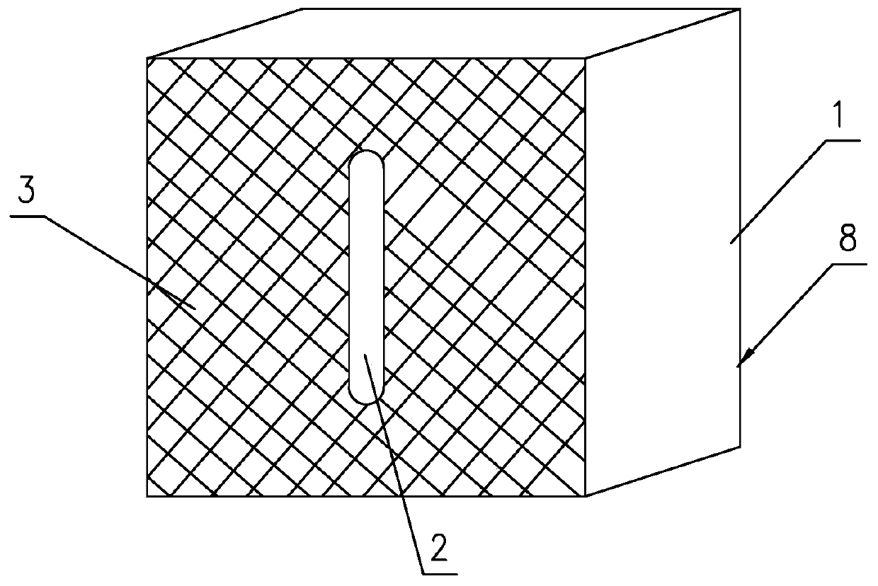
[0032] Such as figure 1 Shown is a heat storage device 8 of the present invention. It includes a shell 1, a solid heat storage material filled in the shell 1 and a heater (not shown in the figure). An air duct 2 is provided in the thermal material. The air duct 2 is a straight air duct. The air duct 2 penetrates the shell 1 and forms an air inlet and an air outlet on the opposite side walls of the shell 1. The shell where the air inlet and the air outlet are located The wall surface of the body 1 is a mesh surface 3, and the mesh diameter of the mesh surface 3 is 2 cm. In this embodiment, the heater is fixed on the inner wall surface of the casing 1, that is, the inner wall surface can be the top surface, left and right sides of the casing 1. The heater is located on the periphery of the air duct 2 and is in the solid heat storage material. Contact with it.

[0033] The solid heat storage material is filled in the shell according to the following heat storage material filling me...


PUM

PropertyMeasurementUnit
Particle sizeaaaaaaaaaa

Abstract

The invention discloses a heat storage material filling method capable of improving the sensible heat storage density of a solid and a heat storage device. The heat storage material filling method comprises the following steps that a small-particle solid heat storage material is laid at the bottom of a housing; a medium-particle solid heat storage material is laid on the small-particle solid heatstorage material; a large-particle solid heat storage material is laid on the medium-particle solid heat storage material; the medium-particle solid heat storage material is laid on the large-particlesolid heat storage material, and the small-particle solid heat storage material is laid on the medium-particle solid heat storage material; and the small-particle solid heat storage material is laidcontinuously, the medium-particle solid heat storage material is laid on the small-particle solid heat storage material, and the large-particle solid heat storage material is laid on the medium-particle solid heat storage material. The solid heat storage material is divided according to the particle size of the solid heat storage material to perform layered filling, and does not need being subjected to press-fit, the void ratio of the solid heat storage material can be reduced to the maximum extent, the solid sensible heat storage density is improved, and the heat storage efficiency is furtherimproved.

Description

technical field [0001] The invention relates to a heat storage material filling method for increasing solid sensible heat storage density, and also relates to a heat storage device using the heat storage material filling method. Background technique [0002] Sensible heat storage is the heat absorbed or released when the temperature of the substance rises or falls, while the nature of the substance itself does not change. Sensible heat storage materials are divided into liquid and solid. Commonly used high-temperature solid sensible heat storage materials are gravel, sand, brick, ceramics, glass, iron, aluminum, concrete, ore, and magnesia bricks. [0003] For high temperature solid sensible substances, the heat transfer medium or the medium used to absorb thermal energy or absorb heat from an external source is a fluid substance. The heat transfer fluid can be water, air, any hydrocarbon fluid (such as thermal oil), molten salts (such as sodium nitrate, potassium nitrate, ...

Claims


Application Information

Patent Timeline
IPC IPC(8): F28D20/00
CPCF28D20/0056Y02E60/14
Inventor 寇翠青柳一曼
Owner 河北创实电力科技有限公司
Why Eureka
Try Eureka