Layered monitoring target for rock and soil and construction method

A construction method and technology of rock and soil mass, which is applied in the field of foundation soil survey, measuring device, and foundation structure engineering, etc., and can solve the problems that the absolute deformation of rock and soil mass cannot be measured, the data reliability is low, and the applicable depth is limited. , to achieve the effects of low cost of measuring equipment, high data reliability, and large application depth

Pending Publication Date: 2019-12-20
徐州中矿岩土技术股份有限公司
View PDF0 Cites 0 Cited by
  • Summary
  • Abstract
  • Description
  • Claims
  • Application Information

AI Technical Summary

Problems solved by technology

[0006] The advantage of this test principle is that the construction is simple, but it also has great limitations: 1. The reliability of the data is low. Since the mortar body in the hole and the surrounding rock and soil are two kinds of media, when the rock and soil are displaced , it remains to be discussed whether the internal mortar body can deform simultaneously with the rock and soil mass
2. The measured data is a relative value. During the measurement process, the measured data is relative to the orifice. When deformation occurs in the deep part of the rock and soil mass, the orifice also sinks accordingly. Under such conditions , the absolute deformation of the rock and soil mass cannot be measured
3. It is inconvenient to monitor. The instrument needs to be lowered into the hole when measuring. When there are many holes to be monitored, the measurement efficiency is low
4. The applicable depth is limited. Due to the applicable depth limitation of the measuring target, the applicable depth limitation of the measuring instrument, and the requirements of the sealing cement slurry construction process, the current depth displacement monitoring depth is about 50 meters

Method used


Image

  • Layered monitoring target for rock and soil and construction method
  • Layered monitoring target for rock and soil and construction method
  • Layered monitoring target for rock and soil and construction method

Examples


Embodiment 1

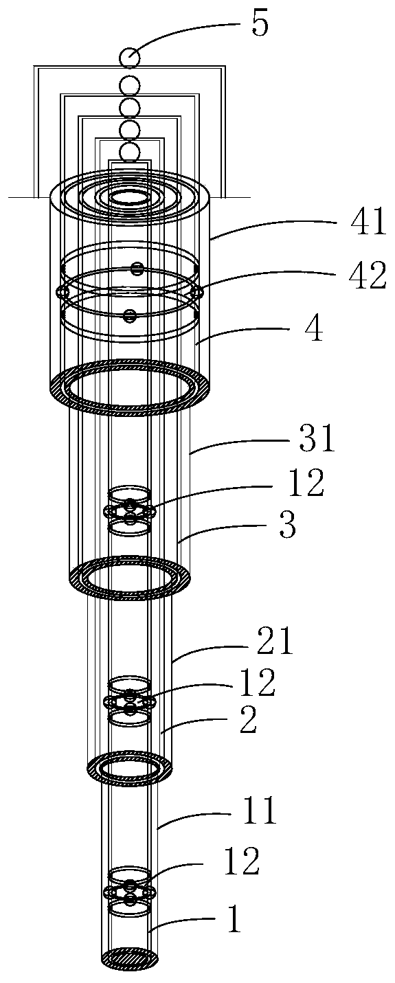
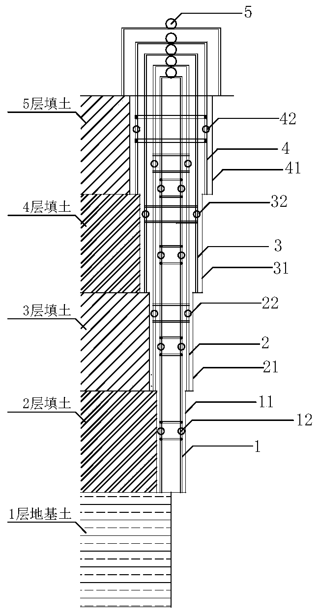
[0043] refer to figure 1 , figure 2 As shown, a 4-level layered monitoring standard for rock and soil in a high fill formed by artificial activities, including 4-level monitoring pipes 1-4, centralizer joints arranged on each level of monitoring pipes, and located at each level The protection tube outside the monitoring tube and the monitoring prism 5 installed on the top of each level of monitoring tube, each level of monitoring tube is vertically arranged, and its bottom end is supported on the top surface of its corresponding target rock formation.

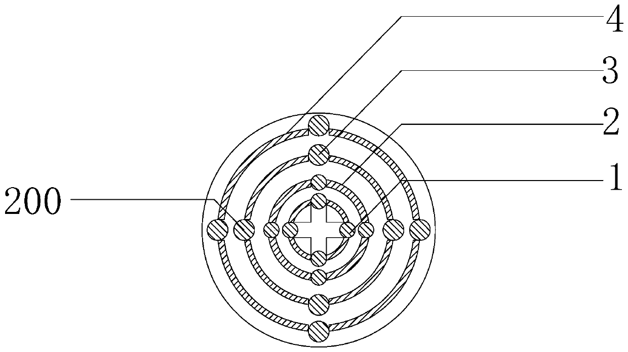
[0044] The 4-level monitoring tubes are the first layer of monitoring tube 1 from the innermost layer, the second layer of monitoring tube 2 set outside the first layer of monitoring tube, and the third layer of monitoring tube set outside the second layer of monitoring tube 2 The tube 3 and the fourth layer of monitoring tube 4 sleeved outside the third layer of monitoring tube 3 are coaxially arranged. The diameter of each ...

Embodiment 2

[0066] The monitoring standard of this embodiment can also be applied to the field of rock formation drilling.

[0067] combine Figure 6 and Figure 7 As shown in Fig. 1, firstly, the monitoring horizon and hole depth are determined according to the design requirements, and the drilling structure is designed. The drilling rig drills to the predetermined layer according to the design level 1 aperture and then washes the well, injects 300% mortar into the hole, the amount of grouting should be 3-5 meters above the bottom of the hole, and runs into the level 1 measuring pipe. Spacing (the distance between the centralizers at the lower part of the monitoring pipe can be relatively dense, and the distance between the upper part can be properly sparse, and the distance between the thin monitoring pipes is smaller than that of the thick monitoring pipes, preferably 3 to 12 meters). The monitoring pipes are connected, and after the grout is solidified, the installation of the first...


PUM


Abstract

The invention discloses a layered monitoring target for rock and soil, and the layered monitoring target comprises a plurality of levels of monitoring tube assemblies for respectively monitoring the deformation of rock layers at different depths, wherein each level of the monitoring tube assemblies respectively comprise vertically arranged monitoring tubes with the bottom ends supported on the topsurface of corresponding target rock formation and monitoring prisms connected to the tops of the monitoring tubes, wherein all the monitoring tubes are arranged coaxially. The invention also discloses a construction method of the layered monitoring target for rock and soil. The invention has the advantages of high reliability of the data, the measured data being the actual sinking value of the monitoring tubes, high monitoring efficiency, good stability of the measuring device, small external influence factors, low cost of the measuring equipment, and the ability to concentrate the tilt measurement and water level measurement functions in a hole (only applicable to the monitoring tube with the smallest diameter in the hole), thereby further saving the monitoring cost.

Description

technical field [0001] The invention belongs to the technical field of underground rock and soil body monitoring, and in particular relates to a layered rock and soil body monitoring standard and a construction method. Background technique [0002] Underground displacement monitoring, also known as deep displacement monitoring, is an important part of geological disaster and geotechnical engineering deformation monitoring. Install and pre-embed underground displacement measurement sensors or monitoring instruments by drilling or other methods. Once deformation such as sliding and settlement occurs inside the underground rock and soil, the underground displacement measurement instruments (sensors) can automatically detect the changes in the above geological structure parameters and complete the process from The measurement process of main geological parameters such as horizontal displacement, vertical displacement and inclination angle at different depths from the surface to ...

Claims


Application Information

Patent Timeline
Patent Type & Authority Applications(China)
IPC IPC(8): G01B21/02G01B21/32E02D1/00
CPCE02D1/00G01B21/02G01B21/32
Inventor 高盛翔王静李晓剑刘钟刘斌岳艳艳许明王占蒙
Owner 徐州中矿岩土技术股份有限公司
Why Eureka
Try Eureka