Virtual tape stacker

a tape stacker and tape stacking technology, applied in the direction of error detection/correction, input/output to record carriers, instruments, etc., can solve the problems of incompatibility between disk storage and tape storage data formats, relatively etc., to achieve the effect of slow data transfer rate, large storage capacity, and low media cos

Active Publication Date: 2010-06-29
ULTRA SYST LTD
View PDF19 Cites 34 Cited by
  • Summary
  • Abstract
  • Description
  • Claims
  • Application Information

AI Technical Summary

Benefits of technology

[0003]The installed base of backup application programs are configured for tape storage. Historically, tape storage is utilized for backup due to low media cost, large storage capacity and removable media characteristics. Tape storage, however, provides relatively slow data transfer rates and can only be accessed sequentially. By contrast, when disk storage is viewed as a tape, it provides relatively fast data transfer rates and random access. Further, advances in disk technology have increased disk performance, storage capacity and data reliability as well as reduced cost. The data formats of disk storage and tape storage, however, are incompatible, as described below. A virtual tape system based upon disk storage technology advantageously converts between tape and disk data formats. Further, by emulating tape devices, the virtual tape system performs this conversion transparently to existing backup application programs.

Problems solved by technology

Tape storage, however, provides relatively slow data transfer rates and can only be accessed sequentially.
The data formats of disk storage and tape storage, however, are incompatible, as described below.

Method used


Image

  • Virtual tape stacker
  • Virtual tape stacker
  • Virtual tape stacker

Examples


embodiment 400

[0042]As shown in FIG. 9A, in one VTC embodiment 400, the device array channels 450 each support either disk or tape storage devices. The channel interfaces 940 provide drivers / receivers for the data path communications channel 450. The channel interfaces 940 are low voltage differential / single-ended (LVD / SE) devices supporting multi-mode LVD or SE operation for SCSI storage devices.

[0043]As shown in FIG. 9B, in an alternative VTC embodiment 400, the device array channels 450 are partitioned between those supporting both disk and tape storage devices and those supporting only disk storage devices. In particular, the channel interfaces 940 are low voltage differential / single-ended (LVD / SE) devices supporting multi-mode LVD or SE operation for SCSI storage devices, which can be either disk or tape. The channel interfaces 945 support IDE disk storage devices only. One data path control logic embodiment 995 functions to provide a single or dual IDE control data path and a single or dual...

embodiment 1000

[0045]FIG. 10 illustrates another, more elaborate data path control logic embodiment 1000 having FIFOs 1005, 1035, a word / byte assembler 1010, a parity generator 1015, a cripple data generator 1020, a router 1025, a comparator 1030, a switch matrix 1040, a DSP interface 1045, a control & status register 1050, a reconstruction 1055, a boundary scan 1060 and a diagnostic port 1065. The data path control logic 1000 has several functions, including routing data bytes / words from a server 110 (FIG. 4) to target channels 450 (FIG. 4) in a “pass thru”, “mirroring”, “striping” or a combination of “mirroring” and “striping” manner; switching data on any or all of the target channels 450 (FIG. 4); generating parity and parity checking; reproducing data for a channel that is being reconstructed and generating pass thru, mirroring, and striping (2+0, 2+1, 2+2, 4+0, 4+1); and providing all of the logic to handle server and target DMA (Direct Memory Access) sequences.

[0046]As shown in FIG. 10, the...


PUM


Abstract

A server interface is adapted to communicate with a server and a data path is adapted to communicate with a random access data storage device. A controller is configured to transfer data between the server interface and the data path. The controller is operational so as to manage the data on the storage device as a plurality of sequentially-ordered virtual tape volumes, wherein a loaded one of the virtual tape volumes is unloaded and a next one of the virtual tape volumes is loaded in response to an eject command from the server.

Description

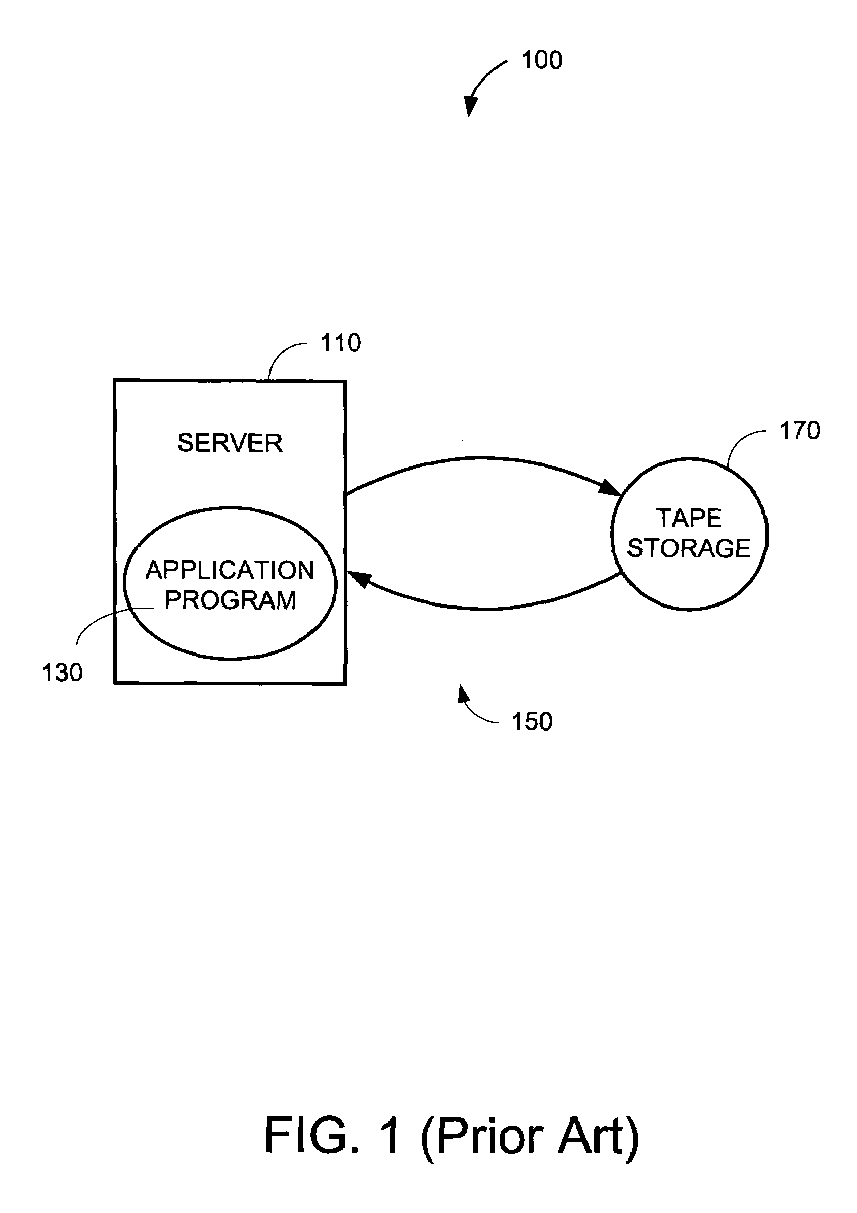
CROSS-REFERENCE TO RELATED APPLICATIONS[0001]This application relates to and claims the benefit of the following prior U.S. Provisional Applications: No. 60 / 459,081 entitled Virtual Tape Controller filed Mar. 31, 2003; Application No. 60 / 473,236 entitled Virtual Tape Library filed May 24, 2003, both applications incorporated by reference herein.BACKGROUND OF THE INVENTION[0002]Computer systems utilize backup to create duplicate copies of programs, disks or data for archiving purposes or to safeguard valuable files from loss should an active copy be damaged or destroyed. FIG. 1 illustrates a conventional tape backup system 100 having a server 110, an application program 130, a communications channel 150 and tape storage 170. The server 110 runs the application program 130 which manages tape storage 170. Tape storage 170 may be one or more tape drive devices or one or more tape library devices. The data channel 150 provides bi-directional communication for transferring commands and da...

Claims


Application Information

Patent Timeline
Patent Type & Authority Patents(United States)
IPC IPC(8): G06F12/00G06F13/28G06F9/26G06F9/34G06F13/00
CPCG06F11/1456G06F2201/815
Inventor NOURMOHAMADIAN, MOHAMADWALCH, JAMES
Owner ULTRA SYST LTD
Why Eureka
Try Eureka