Multi-user virtual tape system

Active Publication Date: 2007-01-09
ULTRA SYST LTD
View PDF9 Cites 72 Cited by
  • Summary
  • Abstract
  • Description
  • Claims
  • Application Information

AI Technical Summary

Benefits of technology

[0003]The installed base of backup, archive and data acquisition application programs are configured for tape storage. Historically, tape storage is utilized for these applications due to low media cost, large storage capacity and removable media characteristics. Tape storage

Problems solved by technology

Tape storage, however, provides relatively slow data transfer rates.
Further, conventional tape storage devices can only be accessed sequentially and thus are limited to one user at

Method used


Image

  • Multi-user virtual tape system
  • Multi-user virtual tape system
  • Multi-user virtual tape system

Examples


Embodiment Construction

Overview

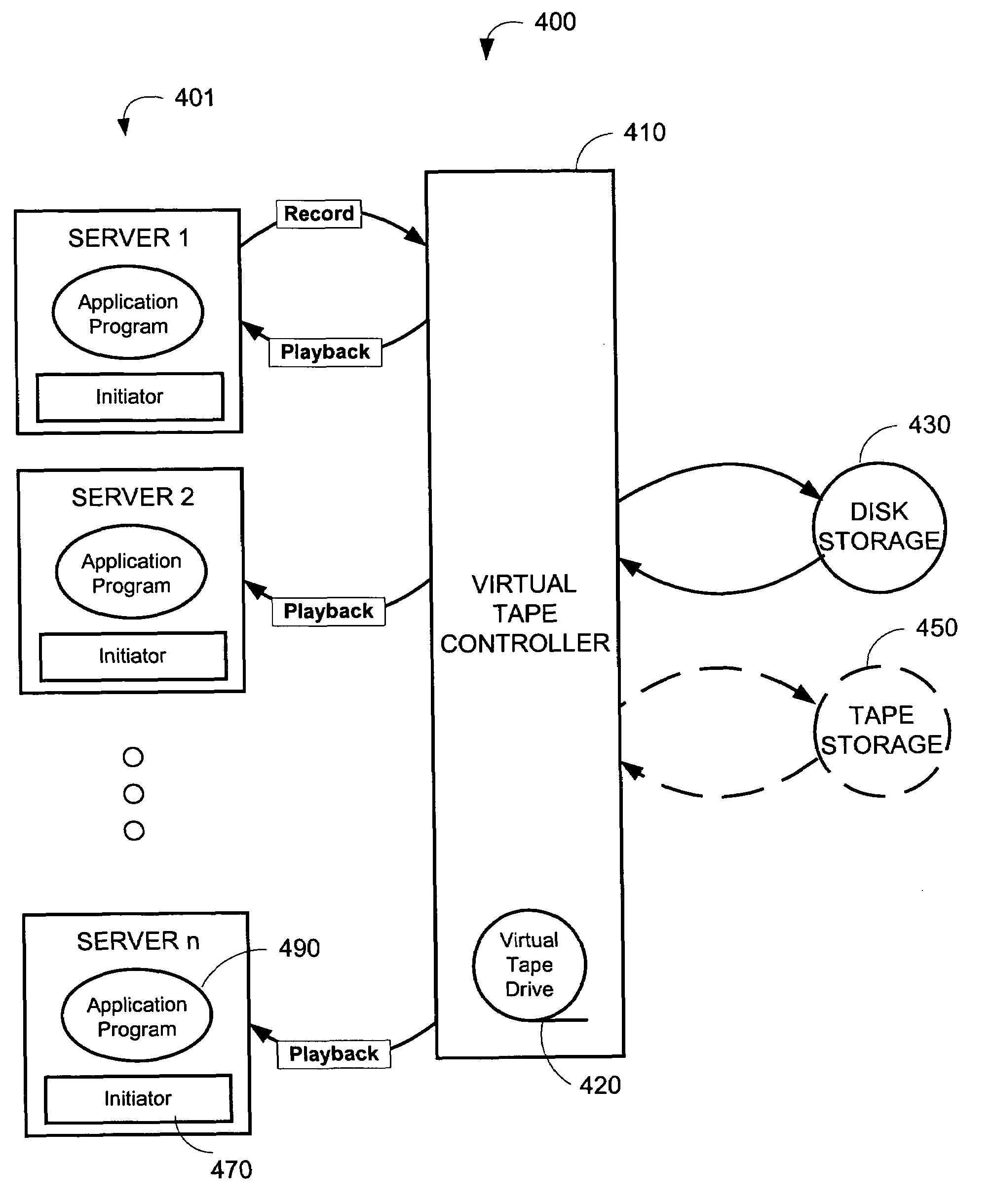
[0021]FIG. 4 illustrates a multi-user virtual tape system 400. A virtual tape system can be advantageously configured as a multi-user tape system due to the random access capability of disk storage systems. As mentioned above, multi-user access is impractical for sequentially-accessed conventional tape storage. A multi-user virtual tape system allows one user to write data while one or more users concurrently read the recorded data. Each tape data block can be read immediately after it is written without interrupting a data acquisition or tape backup process. If an attempt is made to read beyond the last recorded tape block or position beyond the current EOD 319 (FIG. 3) position, a check condition status is posted with error sense data indicating a “blank check” or end of data error. Read operations access new tape data blocks as they become available. A multi-user virtual tape system can utilize multiple host bus initiators or multiple virtual tape drives to concurrently a...


PUM


Abstract

One or more servers are adapted to execute tape application programs. A controller provides communications between the one or more servers and a random access storage device. The controller is configured so that the application programs can concurrently access the random access storage device as a sequential access tape storage device.

Description

CROSS-REFERENCE TO RELATED APPLICATIONS[0001]This application relates to and claims the benefit of the following prior U.S. Provisional Applications: Application No. 60 / 417,024 entitled Dual Access Tape filed Oct. 8, 2002; Application No. 60 / 425,564 entitled Virtual Tape Controller filed Nov. 12, 2002; Application No. 60 / 459,081 entitled Virtual Tape Controller filed Mar. 31, 2003; Application No. 60 / 473,236 entitled Virtual Tape Library filed May 24, 2003, all incorporated by reference herein.BACKGROUND OF THE INVENTION[0002]Computer systems utilize tape storage backup to create duplicate copies of programs, disks or data for archiving purposes or to safeguard valuable files from loss should an active copy be damaged or destroyed. Tape storage is also used for data acquisition and recording and corresponding playback for data analysis. FIG. 1 illustrates a conventional tape storage system 100 having a server 110, an application program 130, a communications channel 150 and tape sto...

Claims


Application Information

Patent Timeline
IPC IPC(8): G06F12/00
CPCG06F3/0607G06F3/0613G06F3/0664G06F3/0686G06F3/0659G06F11/1456
Inventor NOURMOHAMADIAN, MOHAMADWALCH, JAMES
Owner ULTRA SYST LTD
Why Eureka
Try Eureka