
Gas collection system, environmental monitoring system, unmanned aerial vehicle and working method thereof

An environmental monitoring system and gas collection technology, applied in unmanned aerial vehicles, motor vehicles, remote control aircraft, etc., can solve the problems of limited application of drones, limited to picture shooting, and inability to monitor air quality, and improve intelligence. Improve the level of automation and work efficiency, improve accuracy and reference value, and achieve the effect of strong implementability

Pending Publication Date: 2019-12-20
CHINA AGRI UNIV
View PDF0 Cites 6 Cited by
  • Summary
  • Abstract
  • Description
  • Claims
  • Application Information

AI Technical Summary

Problems solved by technology

Nowadays, some environmental monitoring systems can no longer meet the requirements of social development, and technical upgrading is urgently needed
[0004] Unmanned aerial vehicles have excellent characteristics such as not being restricted by ground factors, flexible maneuvering, low cost, fast and three-dimensional execution of tasks. In recent years, with the rapid development of UAV technology, the application of UAVs has gradually entered all walks of life. , but the current application of UAVs in environmental monitoring is still very limited, most of them are limited to screen shooting, and cannot effectively monitor the air quality in a certain area. The monitoring system is a problem that those skilled in the art need to solve

Method used

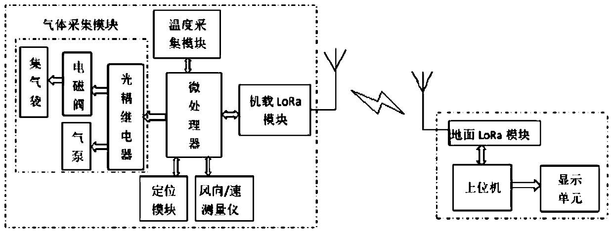
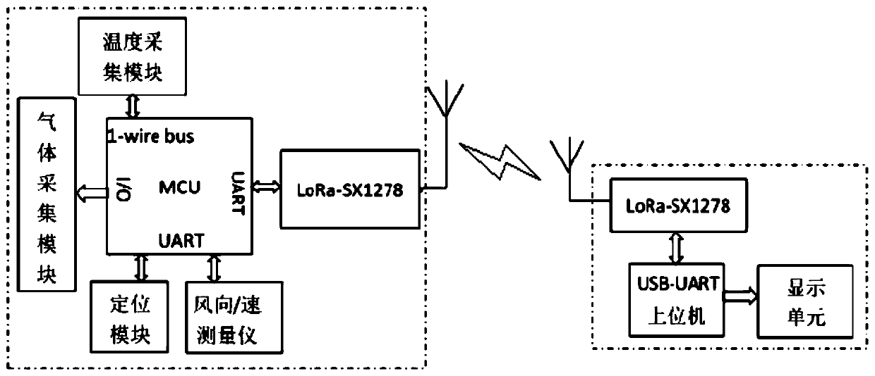
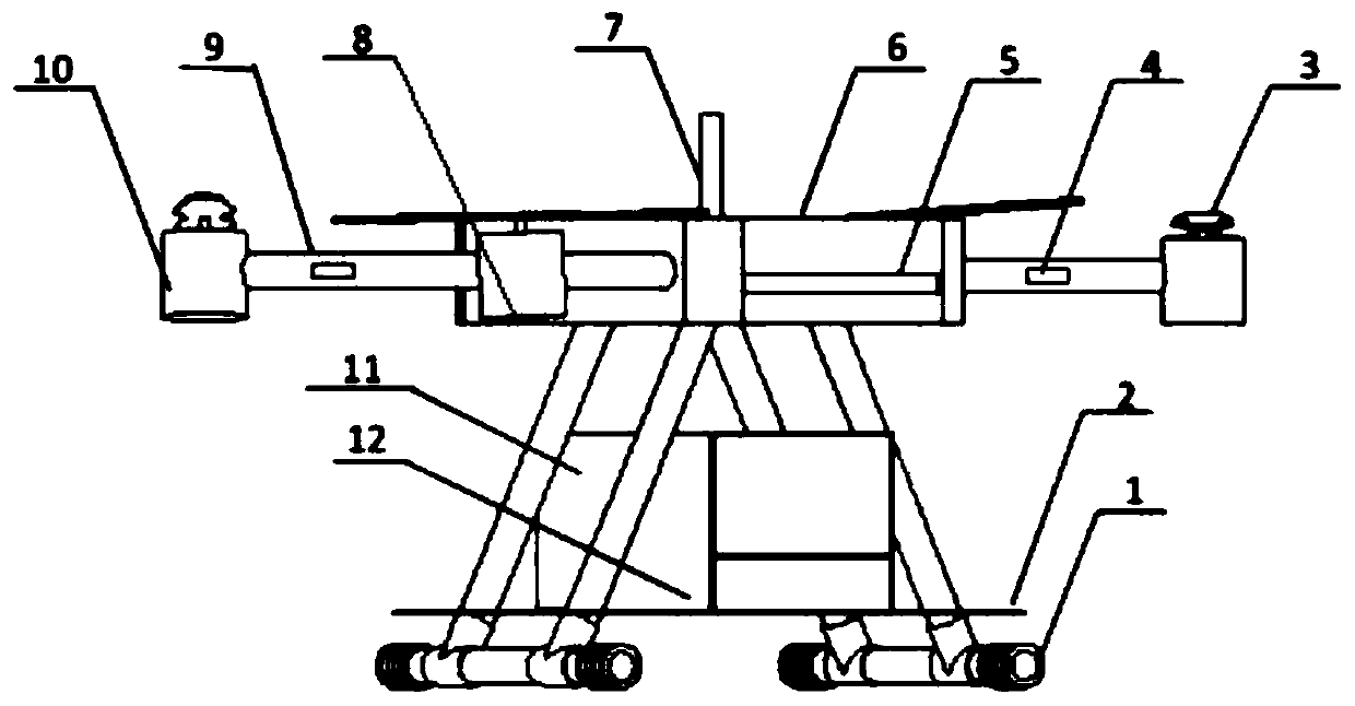

Image

  • Gas collection system, environmental monitoring system, unmanned aerial vehicle and working method thereof
  • Gas collection system, environmental monitoring system, unmanned aerial vehicle and working method thereof
  • Gas collection system, environmental monitoring system, unmanned aerial vehicle and working method thereof

Examples


Embodiment Construction

[0045] The technical solutions of the present invention will be clearly and completely described below in conjunction with the accompanying drawings. Apparently, the described embodiments are some of the embodiments of the present invention, but not all of them. The components of the embodiments of the invention generally described and shown in the figures herein may be arranged and designed in a variety of different configurations. Accordingly, the following detailed description of the embodiments of the invention provided in the accompanying drawings is not intended to limit the scope of the claimed invention, but merely represents selected embodiments of the invention.

[0046] Based on the embodiments of the present invention, all other embodiments obtained by persons of ordinary skill in the art without making creative efforts belong to the protection scope of the present invention.

[0047] In the description of the present invention, it should be noted that the terms "c...


PUM


Abstract

The invention discloses a gas collection system, an environmental monitoring system, an unmanned aerial vehicle and a working method thereof, and belongs to the technical fields of environmental monitoring and protection. The gas collection system comprises a power supply, an air pump and a plurality of air bags, wherein the air pump is connected with the air bags through hoses, each air bag is respectively correspondingly provided with an electromagnetic valve, each electromagnetic valve is respectively connected with a corresponding branch optical coupling relay, one end of the air pump is connected with the electromagnetic valves, and the other end of the air pump is connected with a common optical coupling relay; and the power supply is connected with the air pump and the electromagnetic valves and supplies power for the air pump and the electromagnetic valves. The invention also discloses the environmental monitoring system comprising the gas collection system, the unmanned aerialvehicle carried with the environmental monitoring system and a working method of the environmental monitoring system. Through the technical scheme provided by the invention, trace gas collection, unknown gas collection or gas collection work when the measuring range of a site gas sensor is exceeded and cannot be measured can be realized, the flexibility is high, and the accuracy of environmentalmonitoring data is greatly improved.

Description

technical field [0001] The invention belongs to the technical field of environmental monitoring and protection, and specifically relates to a gas collection system, an environmental monitoring system, an unmanned aerial vehicle and a working method thereof. Background technique [0002] With the vigorous development of social economy, environmental pollution is becoming more and more serious, especially in industries such as industry, agriculture, construction and transportation. At the same time, with the expansion of breeding scale and the substantial increase in car ownership Many places in the country are facing the huge challenge of serious pollution. [0003] However, at present, most of the environmental pollution monitoring points are fixed points, which cannot monitor the areas far away from the monitoring points, which in turn affects the improvement of the air quality and the environment of those far away from the monitoring points. Therefore, there is a need for...

Claims


Application Information

Patent Timeline
Patent Type & Authority Applications(China)
IPC IPC(8): G01N1/24G01N33/00G01D21/02B64C39/02B64D31/00
CPCG01N1/24G01N33/0054G01D21/02B64C39/024B64D31/00B64U10/10B64U2101/00B64U50/19
Inventor 董仁杰徐宁宁
Owner CHINA AGRI UNIV
Learn More