Backlight device and display equipment

A backlight device and light distribution technology, applied in optics, nonlinear optics, instruments, etc., can solve problems such as difficulty in improving uniformity, difficulty in suppressing light quantity decline, etc., to achieve the effect of reducing the diffusion angle, improving utilization efficiency, and optimizing uniform light output

Inactive Publication Date: 2019-12-20
SHENZHEN LONGLI TECH CO LTD
View PDF6 Cites 3 Cited by
  • Summary
  • Abstract
  • Description
  • Claims
  • Application Information

AI Technical Summary

Problems solved by technology

Therefore, it is difficult to improve the uniformity of planarly irradiated light.
In partic

Method used


Image

  • Backlight device and display equipment
  • Backlight device and display equipment
  • Backlight device and display equipment

Examples


Example Embodiment

[0032] Example 1

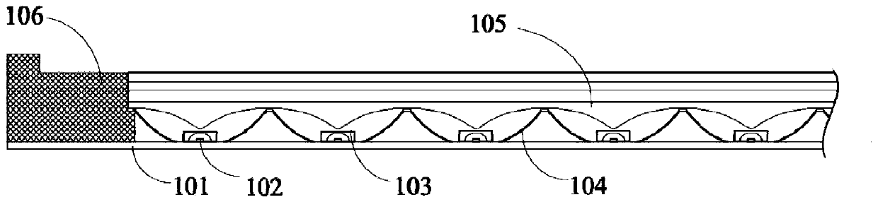
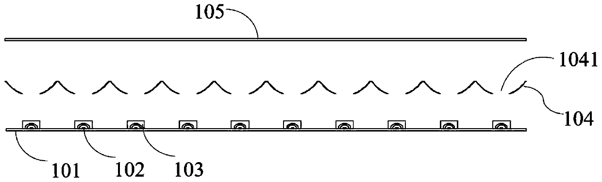
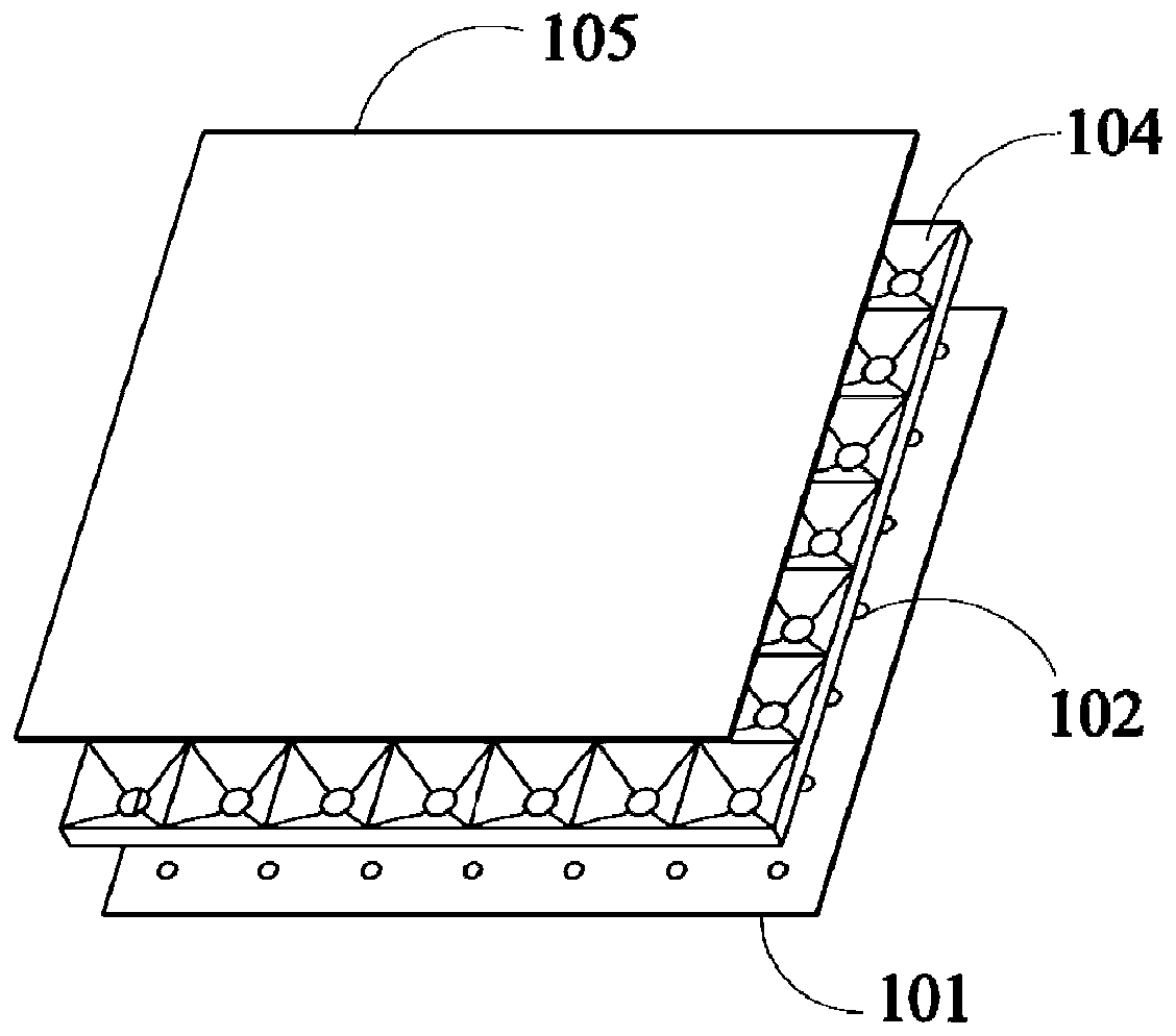
[0033] First, through Figure 1-6 , the backlight device according to Embodiment 1 of the present invention will be described. The backlight device of Embodiment 1 of the present invention includes a substrate 101 , a plurality of LED light sources 102 , a concave lens structure 103 , a reflection cup structure 104 and an optical film 105 . The concave lens structure 103 is used to distribute the light emitted by the LED light source 102 . The optical film 105 is disposed above the concave lens structure 103 . A substrate 101 on which a plurality of LED light sources 102 are mounted. like Figure 4 and Figure 5 As shown, a plurality of reflective cup structures 104 are integrally formed into a reflective plate 204 . The reflective cup structure 104 is provided with an opening 1041 at its bottom, and the LED light source 102 and the concave lens structure 103 are arranged in the opening 1041, so that the reflective cup structure 104 distributes light o...

Example Embodiment

[0038] Example 2

[0039] Please refer to Figure 7 , is an exploded view of a backlight device according to Embodiment 2 of the present invention. Only the differences between Embodiment 2 and Embodiment 1 will be described below, and the similarities will not be repeated here.

[0040] The diffusion film is provided with a convex lens structure corresponding to the reflection cup structure 104 . The convex lens structure on the diffusion film serves as a light diffusion unit to uniformly scatter the light from the LED light source 102 and the reflective cup structure 104, so as to realize uniform light output from the surface light source of the backlight device.


PUM


Abstract

The invention discloses a backlight device and display equipment. The backlight device comprises a plurality of LED light sources, a substrate, a concave lens structure, an optical diaphragm and a reflector cup structure, wherein the concave lens structure is used for distributing light emitted by the LED light sources; the optical film is arranged above the concave lens structure; the LED light sources are mounted on the substrate; the reflector cup structure is used for reflecting a part of distributed light of the concave lens structure toward one side of the display surface of the backlight device; a concave surface of the concave lens structure is arranged on the light emitting sides of the LED light sources; openings are formed in the bottom of the reflector cup structure, and the LED light sources and the concave lens structure are arranged in the openings. The invention provides a backlight device capable of improving uniform light output of a surface light source, and the utilization efficiency of light is improved.

Description

technical field [0001] The invention relates to a display device, in particular to a backlight device and a display device. Background technique [0002] The liquid crystal panel itself included in the liquid crystal display device does not emit light. Therefore, in the liquid crystal display device, a backlight device serving as a surface light source device is provided on the back side of the liquid crystal panel as a light source for illuminating the liquid crystal panel. [0003] As a structure of such a backlight device, a direct type backlight device in which a plurality of light emitting diodes (Light Emitting Diodes: hereinafter referred to as "LED elements") are arranged is known. [0004] In recent years, high-efficiency, high-output, and compact LED elements have been developed. Therefore, even if the number of LED elements or LED BARs used in the backlight device is reduced, the same luminance as before can be theoretically obtained. In addition, LED BAR is fo...

Claims


Application Information

Patent Timeline
IPC IPC(8): G02F1/13357
CPCG02F1/133603G02F1/133605G02F1/133606G02F1/133607G02F1/133614
Inventor 张小齐庄世强李伟
Owner SHENZHEN LONGLI TECH CO LTD
Why Eureka
Try Eureka