Ultrasonic flaw detection method

A detection method, ultrasonic flaw detection technology, applied in the use of sound waves/ultrasonic waves/infrasonic waves to analyze solids, measuring devices, and use sound waves/ultrasonic waves/infrasonic waves for material analysis, etc., which can solve the problems of poor near-surface resolution, high defect missed detection rate, High labor intensity and other problems, to meet the requirements of high signal-to-noise ratio, improve detection efficiency, and reduce labor intensity

Pending Publication Date: 2022-06-28
CHANGSHA ADVANCED MATERIALS IND RES INST CO LTD
View PDF0 Cites 0 Cited by
  • Summary
  • Abstract
  • Description
  • Claims
  • Application Information

AI Technical Summary

Problems solved by technology

[0006] The invention aims to solve the problems of large detection blind area, poor near-surface resolution, low signal-to-noise ratio, high defect missed detection rate, and high labor intensity in the implementation process of the existing flaw detection technology.

Method used


Image

  • Ultrasonic flaw detection method
  • Ultrasonic flaw detection method
  • Ultrasonic flaw detection method

Examples


Embodiment 1

[0039] The present invention will be described in detail below by taking the rare earth magnesium alloy extruded sheet (specification 25*70*315, unilateral machining allowance of 5mm) developed by our company as an example.

[0040] Surface cleaning of the inspected parts: Use clean non-woven fabrics to clean the surface stains, attachments and other unfavorable factors that affect the incidence of sound energy along the direction of the extrusion flow line on the surface of the plate. The cleaning standard is no obvious dust, clean and tidy.

[0041] In this example, Olympus EPOCH 650 ultrasonic flaw detector (providing a 0-25MHZ frequency band) is used. The probes are DA5P10FS10 double crystal straight probes and 5Z14N single crystal straight probes, and the couplant is No. 46 anti-wear hydraulic oil.

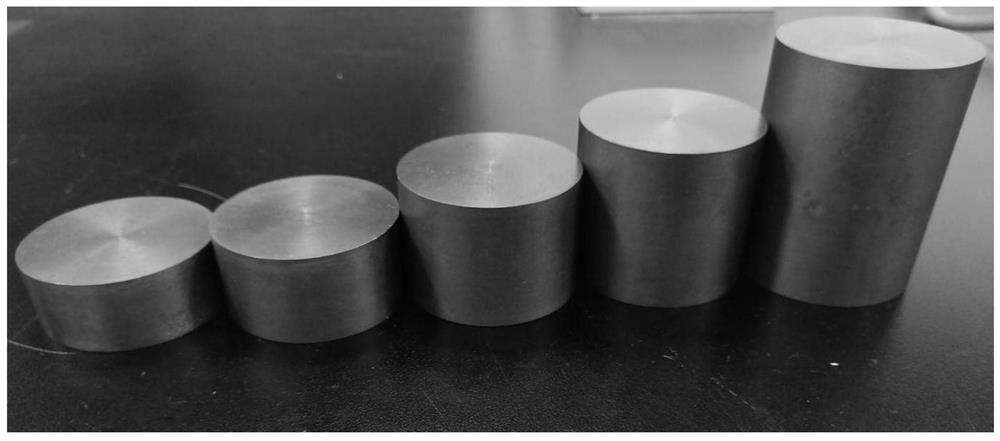
[0042]The flat-bottom hole comparison test block for flaw detection is designed to have a buried depth of 5mm, 10mm, 15mm, 20mm, and 25mm; the hole diameter is φ2.0mm, and oth...

Embodiment 2

[0048] The present invention will be described in detail below by taking the rare earth magnesium alloy extruded sheet (specification 10*175*1800 machining allowance of 2mm) developed by our company as an example.

[0049] Surface cleaning of the inspected part: Use clean non-woven fabrics to clean the surface stains, attachments and other unfavorable factors that affect the incidence of sound energy along the direction of the extrusion flow line on the surface of the plate. The cleaning standard is no obvious dust, clean and tidy.

[0050] In this example, Olympus EPOCH 650 ultrasonic flaw detector (providing a 0-25MHZ frequency band) is used. The probes are DA5P10FS10 double crystal straight probes and 5Z14N single crystal straight probes, and the couplant is No. 46 anti-wear hydraulic oil.

[0051] The flat-bottom hole test block that has been designed and manufactured in Example 1 is selected as the test block for flaw detection, with a buried depth of 5mm, 10mm, 15mm, 20mm...


PUM

PropertyMeasurementUnit
pore sizeaaaaaaaaaa

Abstract

The invention relates to an ultrasonic flaw detection method, and systematically provides a longitudinal wave flaw detection method adopting a high-frequency bicrystal normal probe, a bicrystal high-frequency probe is adopted for detection, a single-crystal normal probe is adopted for transmission correction compensation, and the detection accuracy can be obviously improved through combined use of the two probes; furthermore, the focal length and the size of the bicrystal normal probe are correspondingly selected according to the product size and the detection effect, so that technicians can quickly respond to detection, the efficiency is improved, and the stability of the detection result is ensured. According to the invention, the single crystal normal probe is adopted to carry out transmission correction measurement on the near-field region by adopting the unequal-thickness test blocks, and the method for measuring the transmission correction compensation by adopting the single crystal normal probe in the near-field region is creatively provided, so that the influence of focusing during direct measurement of double crystals is reduced, the material attenuation is correctly evaluated, and the reliability of the transmission correction compensation is ensured.

Description

technical field [0001] The invention belongs to the technical field of ultrasonic flaw detection, and in particular relates to an ultrasonic flaw detection detection method. Background technique [0002] Magnesium alloy materials have the advantages of low density, high specific strength and stiffness, good electrical and thermal conductivity, good electromagnetic shielding, good damping and shock absorption, and easy forming and processing. They are widely used in aerospace weapons and equipment and other parts. In addition, with the upgrading of materials in the civil market, automobile industry, and 3C industry, the advantages of magnesium alloys in light weight and weight reduction are becoming more and more obvious. Compared with steel, the weight can be reduced by about 1 / 3, and compared with steel, the weight can be reduced by about 3 / 4. The market prospect is broad, and it is known as "green engineering materials in the 21st century". [0003] Pure magnesium is ofte...

Claims


Application Information

Patent Timeline
Patent Type & Authority Applications(China)
IPC IPC(8): G01N29/24G01N29/04
CPCG01N29/24G01N29/041G01N2291/0231G01N2291/0421
Inventor 倪立波张涛康心锴
Owner CHANGSHA ADVANCED MATERIALS IND RES INST CO LTD
Why Eureka
Try Eureka