Supercharge Your Innovation With Domain-Expert AI Agents!

Method for a phase calibration of a near field communication NFC device, device and system

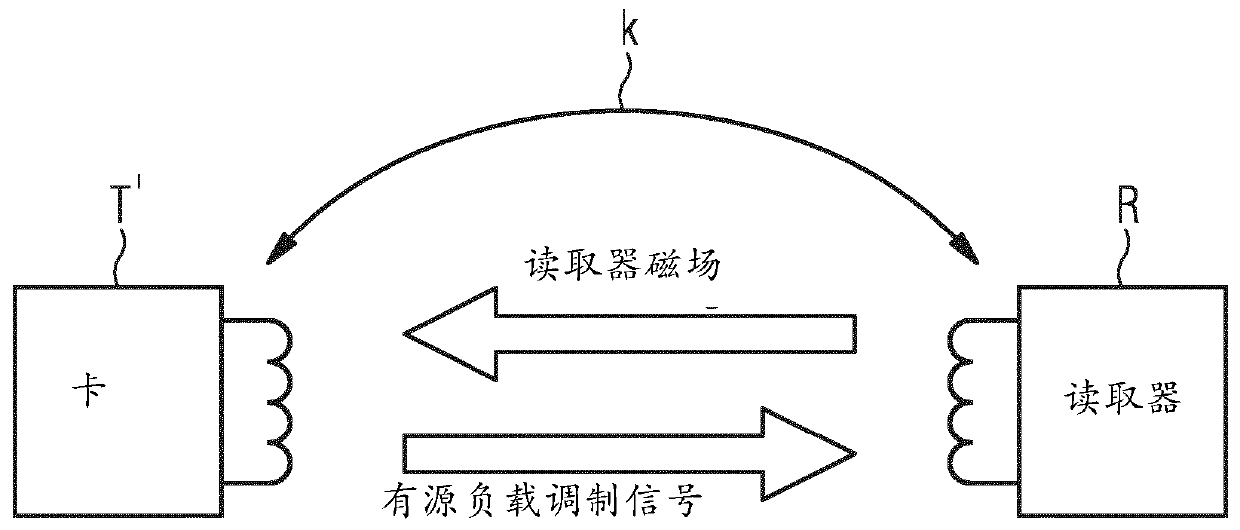
A kind of equipment and phase difference technology, which is applied in near-field transmission system, near-field transmission system in radio frequency identification system, read/write/query/recognition near-field transmission system, etc., can solve the problem of long test time and so on

Active Publication Date: 2019-12-20
STMICROELECTRONICS SRL
View PDF10 Cites 2 Cited by
  • Summary
  • Abstract
  • Description
  • Claims
  • Application Information

AI Technical Summary

Problems solved by technology

Although currently used equipment is based on the automation of sweeping phase settings in labeling equipment, the achievable test times are still too long

Method used


Image

  • Method for a phase calibration of a near field communication NFC device, device and system
  • Method for a phase calibration of a near field communication NFC device, device and system
  • Method for a phase calibration of a near field communication NFC device, device and system

Examples


Embodiment Construction

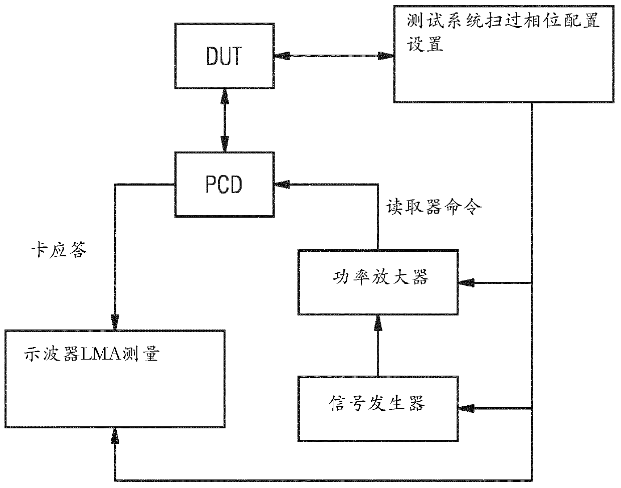
[0096] Figure 4 A first exemplary embodiment of a phase calibration method according to the proposed principle is shown.

[0097] In step S1, the front-end circuit receives the reference signal generated by the NFC test signal generator device.

[0098] In step S2, the front-end circuit receives a phase calibration command. Wherein, the phase calibration command is, for example, provided by the host component of the NFC tag device whose front-end circuit is being phase calibrated.

[0099] In step S3, the front-end circuit generates an active load modulation signal having a pre-configured phase difference with respect to the received reference signal. The different phase difference values ​​used one after the other in the described method are stored beforehand in a memory (for example a register in the front-end circuit). It is also defined in advance: the stored value is used first as a pre-configured or default phase difference value.

[0100] In step S4, the amplitude ...


PUM


Abstract

The application relates to a method for a phase calibration of a near field communication NFC device, a device and system. The method has the steps: receiving a reference signal (Sr) generated by an NFC signal generator device; generating an active load modulation signal (Sf) with a preconfigured value of a phase difference (P1) with respect to the reference signal (Sr) of the NFC signal generatordevice, wherein the phase difference is provided via a register of the NFC device; measuring an amplitude (Vm1) of a test signal (St) present at an antenna of the NFC device, said test signal (St) resulting from overlaying of the reference signal (Sr) with the active load modulation signal (Sf); modifying the value of the register until the measured amplitude fulfils a predefined condition, and storing a chosen value corresponding the value of the register fulfilling the predefined condition.

Description

[0001] This application has an international application date of July 6, 2015, an international application number of PCT / EP2015 / 065352, and a national application number of 201580053345.6, entitled "Phase calibration for the front-end circuit of a near-field communication NFC tag device" Method, front-end circuit and NFC tag equipment" is a divisional application of the invention patent application. technical field [0002] This application relates to Near Field Communication (NFC) in contactless systems. In particular, the present application relates to a method for phase calibration in a front-end circuit of an NFC tag device, a front-end circuit and an NFC tag device. Background technique [0003] NFC tag devices are employed in radio frequency identification (RFID) systems that allow communication between an NFC tag device and a corresponding NFC reader device using inductive coupling. During this communication, the reader mainly sends commands to the tag. The tag the...

Claims


Application Information

Patent Timeline
Patent Type & Authority Applications(China)
IPC IPC(8): G06K7/00G06K7/10H04B5/00H04B17/21
CPCH04B17/21G06K7/0095G06K7/10237H04B5/77H04B5/45H04B5/266H04B5/72
Inventor N·科迪尔
Owner STMICROELECTRONICS SRL
Features
  • R&D
  • Intellectual Property
  • Life Sciences
  • Materials
  • Tech Scout
  • Unparalleled Data Quality
  • Higher Quality Content
  • 60% Fewer Hallucinations
Learn More