A control device and control method for a low-voltage switchgear

A low-voltage switch and control device technology, applied in the direction of measuring devices, circuit devices, emergency protection circuit devices, etc., can solve problems such as inconsistent control of circuit breakers and automatic transfer switch equipment, hidden dangers of accidents, uncoordinated actions, etc.

Active Publication Date: 2021-05-07
SHANXI MINGTUO MECHANNOTROICS TECH CO LTD
View PDF7 Cites 0 Cited by
  • Summary
  • Abstract
  • Description
  • Claims
  • Application Information

AI Technical Summary

Problems solved by technology

[0003] Therefore, the technical problem to be solved by the present invention is: in the low-voltage power distribution system, the control of the circuit breaker and the automatic transfer switch equipment are not unified, and the actions are not coordinated. The transfer switch requires switching to the standby power supply to continue power supply, which brings huge potential accidents to the entire power distribution system. Therefore, the present invention provides a control device for low-voltage switchgear and its control method, which effectively prevents the power supply from still being available when a line failure occurs. resulting in more serious accidents

Method used


Image

  • A control device and control method for a low-voltage switchgear
  • A control device and control method for a low-voltage switchgear
  • A control device and control method for a low-voltage switchgear

Examples


Embodiment 1

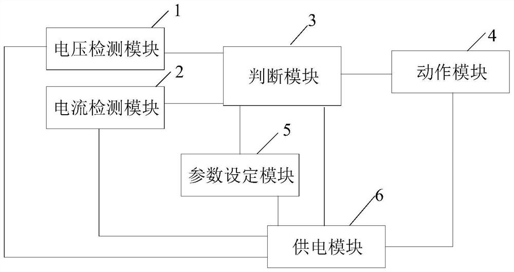
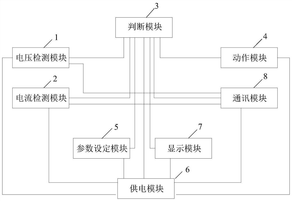
[0035] The embodiment of the present invention provides an automatic transfer switch equipment control device, which can be applied to emergency power supply systems, such as figure 1 As shown, it includes: a voltage detection module 1, a current detection module 2, a judgment module 3, an action module 4, a parameter setting module 5 and a power supply module 6, wherein:

[0036] The voltage detection module 1 is used to detect the voltage, frequency and phase of the normal power supply and the backup power supply. In the embodiment of the present invention, the voltage detection module 1 uses two input transformers and a voltage sampling circuit to detect the common power supply voltage sampling signal, the common power supply frequency sampling signal, the common power supply phase sampling signal, the standby power supply voltage sampling signal, the standby power supply frequency sampling signal and Standby power phase sampling signal.

[0037] The current detection modu...

Embodiment 2

[0062] An embodiment of the present invention provides a method for controlling automatic transfer switch equipment, such as Figure 5 shown, including the following steps:

[0063] Step S1: Acquiring preset reference parameters, the reference parameters include: normal power supply and standby power supply voltage reference parameters, normal power supply and standby power supply frequency reference parameters, normal power supply and standby power supply current reference parameters, and normal power supply side and standby power supply side switches The delay parameter of the action.


PUM


Abstract

The invention discloses a control device and a control method for low-voltage switchgear, wherein the control device comprises: a voltage detection module for detecting the voltage, frequency and phase of a dual power supply; a current detection module for detecting the current of the dual power supply; The module is used to judge the validity of the dual power supply and whether the feeding circuit of the dual power supply is faulty; the action module is used to adjust the switch status of the dual power supply side; the parameter setting module is used to obtain the preset reference parameters; the power supply module is used to It is used to provide power for voltage detection module, current detection module, judgment module, action module and parameter setting module. According to the voltage and current of the dual power supply, the invention judges the validity of the dual power supply voltage and whether the load is faulty, so as to adjust the switching state of the low-voltage switchgear, realizes the coordination and unity of the protection function of the low-voltage power distribution system and the conversion function of the dual power supply, and effectively prevents the In order to avoid more serious accidents caused by the implementation of dual power conversion when there is a line fault.

Description

technical field [0001] The invention relates to the technical field of low-voltage power distribution control, in particular to a control device and a control method with dual power supply automatic conversion function and feeder line protection function. Background technique [0002] In the low-voltage power distribution system, short-circuit, overload, grounding, and lack of phase faults in the power supply circuit rely on circuit breakers and fuses to disconnect the power supply circuit for protection; in a dual-circuit power distribution system with common power and backup power , when the common power supply fails, it relies on the automatic transfer switch to complete the power switching function. The operation of the circuit breaker is controlled by the trip unit, and the operation of the automatic transfer switch is controlled by the controller. When the output terminal of the automatic transfer switch fails, the release will drive the circuit breaker on the common ...

Claims


Application Information

Patent Timeline
Patent Type & Authority Patents(China)
IPC IPC(8): H02J9/06H02H1/00H02H1/06G01R31/00G01R31/52G01R31/58
CPCG01R31/00H02H1/0007H02H1/06H02J9/06Y02B70/30Y04S20/20
Inventor 李兵邢政左鉴波
Owner SHANXI MINGTUO MECHANNOTROICS TECH CO LTD
Why Eureka
Try Eureka